

| Citation: |
Amirhossein Askarian and Ke Wu, “Aperture-Shared Radiation Surface: A Promising Technique for Multifunctional Antenna Array Development,” Electromagnetic Science, vol. 1, no. 3, article no. 0030082, 2023. doi: 10.23919/emsci.2023.0008

|
In the development of a multifunctional and multi-standard analog frontend module in emerging and future wireless systems, multifunction antenna array is an indispensable component. To this end, the aperture-shared technique has come of age, and demonstrated significant advantages in the cost-effective design of efficient, compact, multiband, multibeam, and polarization-diversified antenna arrays, particularly with high frequency ratios. In this paper, various antenna topologies and surface architectures based on this technique, which have been proposed and developed thus far for a wide variety of applications, are reviewed, examined, and categorized to highlight the nature of electromagnetic aperture-shared schemes and merits. Finally, we briefly discuss future research directions in this context for multifunction millimeter-wave and terahertz wireless systems development.
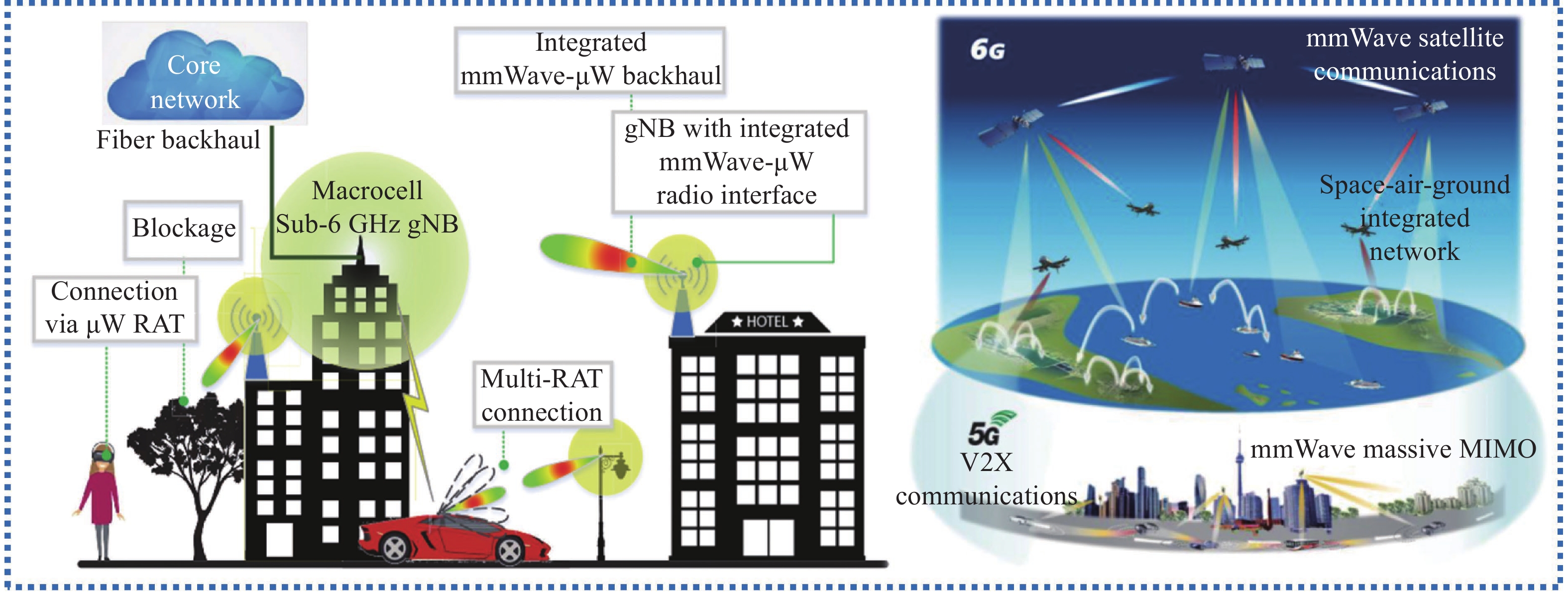
Millimeter-wave (mmW) and terahertz (THz) frequency bands have been selected for and dedicated to the support of B5G and 6G wireless communication systems as a fundamental solution to address the spectrum scarcity issue to improve the capacity/speed of existing wireless systems. In particular, those electromagnetic frequency bands due to their shorter wavelengths and propagation properties, are highly demanded for emerging applications such as imaging, sensing, locating, and spectroscopic systems, which go far beyond the conventional domains of wireless communication, as shown in Figure 1 [1], [2]. However, they suffer from high path loss and low wave penetration in objects, which presents numerous technical hurdles for wireless systems. Radiofrequency (RF) and microwave (MW) frequency bands, in contrast, have the potential to propagate longer in space, as they present lower propagation loss. However, due to the crowded existing spectrum, low data rate transmission and poor spatial resolution in these frequency ranges, they cannot meet current and future requirements. To take full advantage of each allocated frequency spectrum, multiband operation is a viable and promising approach [3].
Obviously, multiband and multistandard operation can be used for a variety of purposes and applications, such as 1) the integration of radar and communication (RadCom) functions in a multifunctional transceiver, which provides a novel low-cost, low-footprint, and power-efficient multifunctional intelligent front-end module, 2) synthetic aperture radar (SAR) applications for acquiring additional information about objects, such as backscattering and penetration information [4]−[6], and 3) in scenarios involving concurrent power transfer and data transmission in an IoT-oriented wireless systems [7]−[9]. Since antennas are used to accomplish such critical functions as the “ears and eyes” of wireless systems, the most important requirement for the forthcoming cutting-edge MW, mmW, and THz multifunctional transceivers is undoubtedly the development of highly efficient, compact, high-gain, and multiband antenna arrays with polarization diversity. Of course, the technical requirements of antenna arrays can differ from one application to another.
Conventional multiband, dual-polarized antenna array architectures based on the independent and side-by-side arrangement of various antenna apertures typically suffer from a bulky size, a low aperture efficiency, and an insufficient isolation level between different frequency bands (caused by strong electromagnetic (EM) mutual couplings and interactions between those antenna arrays). In approximately 1997, the aperture-shared technique was proposed and demonstrated [10] for synthetic aperture radar (SAR) applications, which represents a promising approach for the development of low-cost, low-footprint, and low-weight multifunctional antenna arrays. This is of particular interest for high-aperture-efficiency multiband antenna arrays with a large frequency ratio, using a common antenna aperture. As schematically suggested in Figure 2, this emerging antenna technique can be effectively applied to the development of a low-footprint, multi-functional receiver as well as a cutting-edge multiband analogue radio-over-fiber (ARoF) wireless system [11].
The aperture-shared technique has been studied and exploited over the past years to successfully incorporate diverse antenna operations, such as multiband, multibeam, multipolarization, or any combination thereof, in a shared radiating surface. The conventional approach is based on the proximity or simple interlacing of numerous antenna elements operating in different frequency bands [10]. Generally, this is not an efficient solution strategy for future multifunctional wireless systems. Strong mutual coupling, inter-modulation products, and harmonic components as well as antenna detuning would be some of the undesired or even disastrous consequences of the conventional approach that severely degrade the performance of a transceiver. To address these issues a timely optimization process is imposed on the codesign procedure making this methodology an inefficient design strategy.
In the recently developed and demonstrated innovative aperture-shared concept, each antenna element is “reused” to operate as a multifunctional component that effectively contributes to the operation in entire antenna array frequency bands. In this codesign scenario, all EM interactions (resonance, coupling, and propagation, for example) are utilized to achieve the desired or targeted antenna performance. The ratio of aperture reuse (RAR = Sr/S) is used to measure the performance of this technique, where S is the occupied area of a larger radiating structure (operating in a lower frequency band), and Sr is the occupied area of the radiating structure (operating in a higher frequency band) integrated in the larger radiating structure [12]. In general, various antenna topologies based on the aperture-shared technique can be evaluated and compared using some key factors as figures of merit (FoMs), as shown in Figure 3. Depending on the application scenario, some factors may be more prominent than others. However, the majority of these factors, for instance, 1) the efficiency (including aperture, radiation, and aperture-reused), 2) isolation, 3) radiation pattern (including cross polarization, gain, directivity, side-lobe level, and back radiation), and 4) bandwidth (including impedance, and gain bandwidth), are essential factors that require special consideration during the design stage for a wide range of applications.
In several applications, a specific structure geometry (antenna profile, footprint, and complexity) of an antenna array is not a limiting factor, as it may only increase fabrication costs; however, in an integrated design scenario, this factor becomes a determining and pivotal parameter for selecting antenna types and design methodologies. Therefore, the types of antenna elements, feeding networks, fabrication techniques, antenna geometries, and array arrangements will be determined according to the desired application and performance. Based on the applications, different key factors can be globally considered through a unified metric, namely FoMs in the design stage. For instance, for 5G/B5G MIMO systems, the isolation, polarization, and bandwidth are crucial factors; for antenna on chip (AoC) applications, the antenna footprint and profile (structure geometry) and aperture efficiency are key parameters, and for ARoF applications, the bandwidth and radiation efficiency are key factors that need to be considered through FoMs.
This article reviews and focuses on the technical merits and potential drawbacks of the “aperture-shared” technique in the development of multiband, multibeam, and dual-polarized antenna arrays from a historical perspective up to the most recent research progress in the performance enhancement for various frequency ranges and applications. It is worth noting that this technique has been referred to as or called by a variety of names in the literature, including 1) shared-aperture, 2) aperture-shared/sharing, and 3) common radiating aperture/surface. However, throughout this paper, we refer to it as “aperture-shared”.
In accordance with the open literature, many types of aperture-shared antenna arrays have been proposed and developed in connection with polarization diversity, multiple beams, and frequency bands. As shown in Figure 4, we may essentially categorize the published techniques and structures in terms of polarization including 1) single polarization and 2) dual-polarization consisting of dual-linear polarization and dual-circular polarization in which numerous techniques for planar and nonplanar realizations such as SIWs, metasurface and holographic antenna, Fabry-Perot antennas (2D leaky-wave antenna), transmitarrays, reflectarrays, and metallic waveguides have been used in the demonstration of aperture-shared antennas.
Figure 5 illustrates the evolution of publications on aperture-shared antenna arrays for each major subdivision (according to Figure 4). These trends cover journal and conference articles with contributions from both IEEE and non-IEEE organizations and events. Obviously, this technique was first proposed for the development of a dual-linearly polarized antenna array, which has experienced exponential growth, particularly in recent years. Thereafter, it was applied to the development of linear-polarized (LP) antennas, which have likewise experienced rapid growth. As depicted by the pie graph, single-polarized aperture-shared antenna array-related publications account for almost half of all publications. Subsequently, a linear rise in research and development interests in circularly polarized aperture-shared antennas occurred during the past ten years.
As illustrated in Figure 5, single-polarized aperture-shared antennas have drawn considerable attention in the past few years [12]−[45]. Various antenna elements, such as dielectric resonator antenna (DRA) and patches [13], patch and slot arrays [12], [14], [33], perforated patches [17], patches and square rings [45], gap waveguide antenna arrays [15], patch and grid arrays [16], cavity-backed slot arrays [18], dipole and bowtie arrays [19], [22], Fabry-Perot cavity (FPC) antennas [23]−[27], [29], and metasurfaces [30]−[32], [46], [35]−[39], [41], [42], [44], have been used in the development of dual-band aperture-shared antenna arrays.
A dual-band antenna array operating at 26 GHz and 3.5 GHz was proposed in [13]. A 2×4 substrate-integrated dielectric resonator antenna (SIDRA) array operating at 26 GHz was placed within a 2×2 segmented patch antenna operating at 3.5 GHz. Due to the use of low-profile antenna elements (patch antennas and DRAs), the total profile of the antenna array is 0.03λ0L, where λ0L is the free space wavelength at the lower resonant frequency. To reduce mutual couplings, the DRAs were surrounded by metallic concentric grooves. In addition, the element-to-element spacing was increased up to 0.75λ0 to further diminish mutual couplings. Due to the large interelement spacing, however, the scanning range of this antenna is limited to ±25°. The impedance bandwidth of the antenna is 11.7% and 11.9% for the lower and higher frequency bands, respectively.
Another dual-band aperture-shared antenna array presented in [14] includes a large 3.5 GHz segmented perforated patch antenna and two cavity-backed 1×2 mmW patch antenna subarrays. This low-profile, low-footprint, and dual-band antenna array operates within 3.38–3.64 GHz and 26.4–29.8 GHz with 7.4% and 12.1% impedance bandwidths, respectively. Owing to the use of SIW cavities, high isolation levels are achieved over both frequency bands (45 dB at 3.5 GHz and 40 dB at 28 GHz). Furthermore, the peak gain in the lower band is 6.9 dBi while it reaches 14.36 dBi in the mmW frequency band. The SIW cavity not only improves the isolation level and impedance bandwidth of the antenna array but also enhances the realized gain by creating a high-Q resonance at the operating frequencies.
As mentioned earlier, the ratio of aperture reuse (RAR) is a crucial factor in an aperture-shared antenna array that can be regarded as an FoM. A high RAR value indicates that the antenna aperture is being effectively used in both frequency bands. A dual-band antenna array that operates at 60 GHz and 3.5 GHz was proposed in [12] with a frequency ratio of 17. In this antenna array, a 12×12 SIW slot array operates at 60 GHz while the whole surface of the SIW structure is reused to operate as a large patch antenna working at 3.5 GHz, as shown in Figure 6. As reported, the RAR for this antenna architecture is 0.77. The maximum radiation occurs at the antenna edges in the S-band, whereas the slot antennas etched on the patch antenna surface radiate primarily at the aperture center in the mmW frequency band. With the high-pass nature of the SIW structure and the use of a compact microstrip resonant cell (CMRC) in the feeding line, high isolation levels of approximately 130 dB at 3.5 GHz and 65 dB at 60 GHz are achieved.
Gap waveguide (GW) technology can be adopted in the antenna structure to eliminate substrate loss and develop a high-efficiency and high-gain antenna. It is realized by two parallel plates in which one of them is a metallic surface and the other is a high-impedance surface created by periodic metal nails [15]. This guiding structure confines the EM fields along the propagation path; therefore, the EM leakage is very low. Ferrando-Rocher at el. [15] showed that using GWs in an aperture-shared antenna results in a high-gain and highly efficient dual-band antenna array. The proposed 8×8 antenna array operates in K-band (19.5–21.5 GHz) and Ka-band (29–31 GHz).
As illustrated in Figure 7, the radiating elements in both frequency bands are circular apertures. These circular apertures are realized by GWs in both layers, which are excited in two orthogonal polarizations. A grating lobe is anticipated to appear in the antenna pattern as the antenna operates at two distant frequencies (20 and 30 GHz), which decreases the antenna radiation efficiency. To circumvent this issue, a waffle grid was designed and applied to the antenna aperture, making the aperture fields uniform and eliminating the grating lobe. The realized gain in K- and Ka-bands are 26 dBi and 29.5 dBi, respectively. The peak radiation efficiency of the antenna array is above 85% for both frequency bands.
A multilayer dual-band antenna array operating in S- and Ka-bands was reported for 5G applications in [17]. The perforated patch antenna (S-band element) is fed by proximity coupling and a 3×3 square patch array (operating in Ka-band) was fed by an aperture coupling technique. To improve the impedance bandwidth in the S-band, a square ring antenna was introduced into the topmost layer, which was EM-coupled to the perforated patch antenna. A bandwidth of around 8% and 19% were reported in the S-band and Ka-band, respectively.
Another dual-band aperture-shared antenna array was designed by interlacing bowtie and rectangular slot antennas for low earth orbit (LEO) satellite communication in [18], as detailed in Figure 8. The proposed dual-band antenna array functions in K-band (19 GHz) and Ka-band (29 GHz) with a frequency ratio of 1.5. The 8×8 antenna array functions in K-band consists of 16 substrate-integrated coaxial line (SICL)-fed bowtie slots, while the array in Ka-band includes 16 cavity-backed SIW-fed slot pairs. With reference to Figure 8, since the TE120 mode is excited in the cavity, a pair of slots etched on the top of the cavity are fed in-phase, generating broadside radiation. The SIW and SICL incorporated feeding networks are set to drive the Ka-band cavity-backed slot pair antennas and K-band bowtie slot antennas, respectively. Owing to the use of the SIW cavity, SIW, and SICL transmission lines (TLs), high isolation level (50 dB and 60 dB) and broad impedance bandwidth (14.7% and 20.7%) are achieved in both frequency bands.
As mentioned in [18], the electric field is perpendicular to the cavity-backed slots in Ka-band while it is transverse to the bowtie slots in K-band; therefore, this antenna shows a vertical polarization in Ka-band (with cavity-backed slots) and a horizontal polarization in K-band (with bowtie slots). The peak measured gains were reported as 21.4 dBi and 22 dBi in K-band and Ka-band, respectively. The fabrication of multilayer antenna arrays typically involves a time-consuming, expensive, and sophisticated procedure, which increase the antenna profile, and is therefore not an appropriate solution for all applications. A novel single layer dual band aperture-shared dipole antenna was proposed in [19]. This antenna operates at both 28 GHz and 3.5 GHz with a 20% impedance bandwidth. A 1×4 array of Yagi antennas operating at 28 GHz was integrated in a large dipole antenna operating at 3.5 GHz. To improve the port-to-port isolation levels, a SIW structure was applied to both the Ka-band and S-band feeding lines. The impedance bandwidth of the Ka-band antenna array was improved by introducing an interdigital coupling (IDC) structure. This dual-band antenna with a simple structure showed peak gain of 7.1 dBi and 11.3 dBi in S-band and Ka-band, respectively.
The Fabry-Perot cavity (FPC) antenna or equivalently the 2D leaky-wave antenna concept is popular in antenna design due to its simple structure and ability to generate a highly directive radiation pattern without a complex feeding network [20], [21], [47]−[50]. The operation of this antenna is based on partial leakage of EM waves that propagate radially in a cavity, as shown in Figure 9. The cavity is formed between a ground plane (at the bottom) and a partially reflecting surface (PRS) at the top separated by approximately half a wavelength. The PRS in its classical and conventional form is a metallic surface in which periodic discontinuities (i.e., slots) are etched (inductive PRS) or a planar surface on a dielectric substrate in which tightly coupled square metallic patches are periodically arranged (capacitive PRS). The antenna is generally designed to operate based on the first higher order mode of a parallel plate waveguide [48]; therefore, according to the EM field distribution in this mode, it can be efficiently excited by an electric current (dipole) at the middle of the cavity (where the electric field is maximum) or a magnetic current (etched slot) on the ground plane (where magnetic field is maximum). A uniform/quasi uniform 2D leaky-wave antenna is realized with an air-filled cavity in which radiation is based on the fundamental leaky-wave mode (or equivalently the
Over the past years, the aperture-shared technique has been adopted to the FPC antenna theory for the development of a multiband single and dual-polarized antenna with a large frequency ratio [22]−[29]. The proposed dual-band air-filled FPC antenna in [22] operates within 0.68–1.07 GHz and 1.7–2.7 GHz with 36% and 46.5% impedance bandwidths, respectively. As shown in Figure 10, a cross-bowtie antenna operating in the higher band (called high band antenna (HBA)) was placed under four loop antennas working in the lower band (called low band antenna (LBA)) positioned at the top layer, and then, all antennas were excited by coaxial TLs. In this aperture-shared architecture, the LBA has some shielding effects, which blocks the HBA radiation. To address this issue, the authors added a low-pass 11×11 PRS (capacitive PRS) between the HBA and the LBA. In a transverse equivalent network (TEN) model, the PRS is represented by a shunt capacitor; thereby, the capacitive PRS realizes a low-pass circuit. As result of the low pass nature of the PRS, it is transparent to the low frequencies but opaque to the higher frequencies. Therefore, an FPC antenna was realized with the HBA because the PRS sheet is partially reflective (opaque) in this band while having a minor effect on the radiation of the LBAs (four loop antennas).
Another PRS layer (PRS 2 in Figure 10) was incorporated above the LBA to further improve the antenna performance. As this layer is highly transmissive in the low frequency band and reflective in the higher frequency band, it is set to enhance the gain of the HBA while having no impact on the LBA radiation as shown in Figure 10. A PRS layer can be effectively used in two or more distinct frequency bands with various functions as a multifunctional element. In this case, the aperture reuse ratio approaches unity, which improves the antenna performance. This concept has been reported in [23], in which the top layer serves as a Fresnel zone plate (FZP) or a PRS depending on the frequency band.
With reference to Figure 11, a dual-functional layer (PRS and FZP) was applied in [23] for the development of a dual band aperture-shared antenna operating in the sub-6 GHz (3 GHz) and mmW (28 GHz) bands. An FPC antenna in the sub-6 GHz band was created by printing periodic grid patches on the substrate while an FZP lens was realized by employing periodic double-screen dipoles. These two layers were stacked and unified to form an engineered, dual-functional layer at the top. Therefore, this layer concurrently functions as the PRS of an FPC antenna in the sub-6 GHz band and an FZP lens in the mmW band. To create a high gain FPC in the sub-6 GHz band, the ground plane should be highly reflective. However, this highly reflective ground plane has destructive effects on the mmW band since the consecutive reflections of EM waves between the ground plane and the FZP lens degrade the antenna performance in the mmW band. To solve this issue, instead of a solid metallic plate, a grid-based ground plane was used, as shown in Figure 11. This engineered ground plane is transparent to the mmW band while it is reflective to sub-6 GHz. This technique improves the radiation pattern in the mmW while having minor effects on the sub-6 GHz performance as illustrated in Figure 11. The FPC antenna is excited in the sub-6 GHz by a large patch antenna on the bottom layer, and a WR-34 waveguide, which feeds the patch antenna at 28 GHz, is housed in an opening within the patch antenna. The measured gains are 15 dBi at 3 GHz and 20.4 dBi at 28 GHz.
Metasurface theory and SIW techniques have been investigated over the past years for the development of a multi-band, multipolarized, and multibeam antenna with an aperture-shared technique [30]−[46], [51], as elaborated below. A metasurface-based low-profile (0.04λ0), and dual-band antenna operating in S-band and X-band with a wide beam scanning ability (±50°) has been proposed in [30]. The antenna elements at both bands are square mushrooms (patches with a metallized via at its center). The designed multilayer stacked antenna array consists of 11 elements in a triangular lattice operating in S-band and 8×16 elements in a rectangular arrangement operating in X-band. The S-band elements were placed under the X-band antenna array to avoid radiation blockage. This configuration and architecture allow the antenna to properly operate in both frequency bands without grating lobes during broad beam scanning. The measured gain and impedance bandwidth in S-band are 12.8 dBi and 11.7%, respectively, and these values are 13.7 dBi and 11.1% for the X-band operation.
Although the aperture-shared concept was initially developed to create multiband antenna arrays, it can also be applied to form single-band antenna arrays where multiple radiation beams are generated from a single shared aperture. The use of SIW is a promising and well-known technique that can be effectively applied to generate multiple radiation patterns from a common aperture in an end-fire antenna array. The SIW incorporated feed beamforming network, compact SIW Rotman lens, and Butler matrix-fed SIW antenna array are some of the examples of SIW-based aperture-shared multibeam antenna arrays that can be employed in in-flight satellite communication, automotive radar, and 5G mobile devices [34].
Holographic leaky-wave theory [35] can be applied to establish beamforming-free multibeam and high-gain antennas from a single aperture. The number of beams and their directions are first defined in this technique, and then a corresponding pattern is printed and arranged on a guiding structure. This pattern “modulates” the guided wave as it travels through the antenna structure. Floquet spatial harmonic expansion for periodic events is used to expand the aperture EM field and each field component in this expansion is called a “space harmonic”. In a periodic leaky-wave antenna, the radiation is primarily caused by the
In [35], a novel holographic-based 2D leaky-wave antenna was reported for the generation of four radiation beams from a common surface. Surface waves, which serve as guiding waves in this antenna, are excited at the aperture center by a small monopole antenna. The antenna aperture is then divided into four sections. A sinusoidal-modulated surface impedance based on the holographic theory was realized in each section by printing patches of various sizes. Excited surface waves in each section are modulated in different manners, resulting in the generation of four radiation patterns in four directions. A holographic-based dual-beam and polarization-diversified antenna was described in [37]. The fundamentals of this antenna are similar to [36]; however one pattern in this antenna has the vertical polarization while the other has horizontal counterpart.
A more complicated metasurface-based antenna can be deployed to generate several radiation beams from the surface. Gonzalez-Ovejero et al. [38] proposed a novel methodology for generating multiple beam from a surface without sectorizing the surface. In this technique, all apertures are used for the superposition of several modulations. Each modulation generates a radiation pattern in a specific direction. In addition, a scenario based on multiple sources was investigated in which all radiation beams generated by several sources can be combined to generate a single radiation pattern. This technique could be adopted in some applications such as “spatial power combining”.
Table 1 provides a thorough summary of some published articles on single-polarized aperture-shared antenna arrays, in which the critical factors of these antenna arrays are listed and compared for various antenna topologies and techniques. As shown in this table, the antenna arrays based on FPCs [13], [23], [25], [26], [28], [29] generally provide relatively high gain, and high aperture-reuse efficiency, while these antenna arrays suffer from a high profile structure compared to the other types of arrays. In contrast, waveguide antenna arrays, including gap waveguides [15], SIWs [12] and the antenna arrays in [18], offer high levels of isolation between frequency bands with very low profile structures.
| Ref. | Freq. (GHz) | Antenna type | Peak gain (dBi) | Fractional bandwidth (%) | Peak efficiency (%) | Isolation level (dB) | Scane range (±°) | Antenna profile (λ0) | ||
| Imped. | Gain | Reuse | Rad. | |||||||
| [13] | 3.5/26 | SIDRA/ Patch | 5/12.9 | 11.7/11.9 | – | – | – | 40/18 | 25 | 0.03 |
| [14] | 3.5/28 | Perforated patch/ Patch | 6.9/14.6 | 7.4/12.1 | – | – | – | 45/40 | 30 | 0.04 |
| [12] | 3.5/60 | Patch/SIW slot | 7.3/24 | 2.6/6.4 | –/2.4 | 77 | – | 130/65 | – | 0.02 |
| [15] | 20/30 | Gap waveguide | 26/29.5 | 10/6 | – | – | 85 | – | – | – |
| [18] | 19/29 | Bowtie slot/SIW slot | 21.4/22 | 14.7/20.7 | – | – | 61/33.3 | 60/50 | – | – |
| [19] | 3.5/28 | Dipole/ Dipole | 7.1/11.3 | 20.7/20.5 | – | – | – | 15/15 | 25 | – |
| [22] | ~1/~2 | Air-filled FPC | 8/8 | 36/46.5 | 36/46.5 | – | – | – | – | ~0.5 |
| [23] | 3/28 | FPC/FZP | 15/20.4 | 4.9/7.1 | 6.4/7.1 | ~100 | – | 17/10 | – | – |
| [25] | 0.9/6.5 | Patch/FPC | 9/16.6 | 25.6/30.5 | 25.1/21.3 | 100 | – | 40/22 | – | 0.15 |
| [26] | 5.4/25 | Reflect array/FPC | 15.5/22.4 | 3.6/16 | – | 100 | – | 80/30 | – | 0.54 |
| [28] | 3.45/5 | Patch/FPC | 13.7/16.8 | 1.45/2.2 | 1.45/2.2 | 100 | – | 32.6/41.2 | – | 0.56 |
| [29] | 2.4/28 | Patch/FPC | 8/15 | 4/2 | – | 100 | – | 38/25 | – | – |
| [30] | ~3/~9 | Metasurface | 12.6/4.3 | 10/11.7 | 10/11.1 | – | 91 | 10/21 | 50 | 0.04 |
| [31] | 2.7/5.75 | Patch/Metasurface | 7.9/11.7 | 25.8/3.8 | – | 100 | – | 25/20 | – | – |
| [32] | 3.6/25.8 | Metasurface | 10.88/22.4 | 23.45/4.8 | – | 100 | – | – | – | 0.59 |
 DownLoad:
CSV
DownLoad:
CSV
The channel capacity of a wireless system can be improved by several fundamental techniques such as 1) spatial diversity (i.e., using several antennas operating at the same frequency), 2) frequency diversity (i.e., using a multiband antenna), and 3) polarization diversity (i.e., using a polarization-diversified antenna operating at the same frequency), or any combination of these techniques. Among them, polarization diversity is more spectral and space efficient, and is less sensitive to channel distortions. In this technique, at least two orthogonal polarizations are used to develop a full-duplex data transmission system operating in the same frequency band. It can be effectively used in the development of a compact, low-cost, and spectrally efficient full-duplex transceiver. Thus, the development of a space and power-efficient, low-cost, polarization-diversified antenna array with high levels of isolation between the ports and polarizations is highly desired. In this section, we first review several state-of-the-art methodologies for creating a dual-linearly polarized antenna array, and then, we proceed to a dual-circularly polarized antenna array based on the aperture-shared technique.
The conventional and classical structure of a dual-band and single-beam aperture-shared antenna array realized by a perforated-patch array in the lower band and a square patch array in the higher band is presented in Figure 12. This multilayer architecture is the most prevalent type for SAR applications and has been widely reported in the literature [10], [52]−[59]. The perforated antenna array at the top is transparent to the radiation of the patch antenna array in the bottom layer. This technique was applied in [10], [53] to develop a dual-band and dual-polarized antenna array operating in the L-band and C-band with an impedance bandwidth of 100 MHz and scanning range of ±25°. One of the fundamental challenges for this type of antennas is to handle and govern mutual couplings between the antenna elements operating in the higher frequency band (square patch array) and the feeding network of the lower-band array, which are both housed on the same substrate. To address this issue, the interelement spacing is typically selected as 0.8λ0 or 0.9λ0, which, in turn, reduces the array scanning ability.
A dual-band antenna array operating in S-band and X-band was designed in [54] using a stacked dipole antenna and square patches. In this configuration, the impedance bandwidths for the low band (S-band) and high band (X-band) are 9% and 17%, respectively. Perforated patches, stacked patches, and slim crosspatches were utilized to develop a tri-band (X/Ku/Ka-bands) aperture-shared antenna array in [59] with impedance bandwidths of 3.6%, 6.7%, and 5.3%. Although this type of antenna array architecture and topology is very compact and allows for a wide range of frequency band selections, it suffers from low impedance bandwidth, scanning range, and poor isolation.
In recent years, more advanced and sophisticated techniques have been applied to develop multiband and dual-polarized aperture-shared antenna arrays with improved performance (e.g., isolation level, bandwidth, gain, and radiation and aperture efficiency) using more complex fabrication processes and technologies [56], [57], [60]−[74]. In [60], a dual-band and dual-polarized antenna with vertical and horizontal polarizations was proposed for operation in Ka-band (33–34 GHz) and Ku-band (15–17 GHz) with a scanning range of up to ±50°. Figure 13 shows a unitcell along with radiation patterns of the antenna containing both Ka- and Ku-band dipole antennas. With reference to this Figure, to compensate for the shading effects of Ku-band antennas on Ka-band antennas and improve the scanning ability, parasitic directors were loaded in the Ka-band to increase the height of the phase center in these antennas. The advantage of this antenna array is that it provides a reasonable impedance bandwidth while also offering a high realized gain and a wide scanning range in both frequency bands. The peak gains of the antenna in Ku-band and Ka-band are 19.7 dBi and 22.8 dBi, respectively.
A more complicated structure was designed in [62] for dual-band operation in S-band (2.4 GHz) and V-band (60 GHz) with a frequency ratio of 17. A large patch antenna radiates in S-band and an orthogonal long-slot array etched on the large patch radiates in V-band. Therefore, the surface of the large patch antenna is “reused” for creating slot antenna array in V-band. A circular V-band SIW-based structure with five ports was used to feed the V-band antenna, as shown in detail in Figure 14. Since the antenna is differentially fed in both frequency bands, a stable beam direction (particularly in V-band) is observed over the frequency band of interest. With reference to Figure 14, the five-port hybrid junction consists of a vertical cylindrical TL connected to a circular cavity.
Two differential ports (i.e., 2 and 3 as well as 4 and 5) excite two degenerate modes (i.e., TE11(1) and TE11(2)) in the circular cavity. Then, the cavity is connected to the SIW power dividers on the top layer through port 1. At 2.5 GHz, a quarter-wavelength coaxial cavity excites the TM01 mode of the top patch antenna. This antenna shows peak gains of 27.8 dBi in V-band and 8 dBi in S-band.
The isolation levels in S-band and V-band are better than 25 dB and 55 dB, respectively. Although this antenna shows a high gain and a high isolation level, it still suffers from low impedance bandwidth. The impedance bandwidths in S-band and V-band are approximately 3.27% (2.4 to 2.48 GHz) and 3.5% (59.7 to 61.3 GHz), respectively.
The impedance and pattern bandwidths are improved by the concurrent use of magnetic and electric currents (a Huygens source) in antenna design. This type of antenna is called magnetoelectric dipole (ME-dipole) or complementary antenna in literature. In fact, this antenna is well-known for its broad impedance and gain bandwidth, low cross-polarization, and high radiation/aperture efficiency. Although this type of antenna has been investigated and developed with a variety of architectures and structures, a conventional type is basically realized by using an orthogonal arrangement of a half-wavelength dipole and a quarter-wavelength patch antenna, which serve as electric and magnetic currents, respectively [75]. In this scenario, slot and dipole modes are properly coupled, realizing multimode resonances and wide impedance and gain bandwidths.
An aperture-shared dual-band and dual-polarized antenna based on an ME-dipole antenna was proposed in [64] for 5G communication systems. The antenna operates at 2.35 to 3.93 GHz and 24 to 34 GHz with 50.31% and 33.91% impedance bandwidths, respectively. A 2×2 ME-dipole antenna array operating in the higher frequency band was designed within a large SIW rectangular cavity. Through a proper arrangement of the four ME-dipole antennas, a larger ME-dipole antenna was realized that operates in the lower frequecy band.
Therefore, the 2×2 ME-dipole antenna array was “reused” to create a larger antenna. Two degenerate-modes TE120 and TE210 are excited in the SIW cavity for a dual-polarized operation. Four horn antennas with tilted inner walls were then placed over the four small ME-dipole antennas (a 2×2 array) to increase the realized gain of the array. The antenna peak gains are 10.67 dBi at 3.8 GHz and 14.85 dBi at 32.2 GHz. Although high realized-gains and broad impedance bandwidths were reported for this antenna, the scanning range of this antenna is limited to ±20°.
A high-gain antenna operating in X-band and Ka-band was developed in [24] using the FPC concept in conjunction with a transmitarray (TA). According to Figure 15, the top layer, or shared surface, serves two functions: 1) as a PRS (an opaque surface) for the FPC antenna operating in X-band, and 2) as a phase shifting surface (a transparent surface with a small attenuation) for the TA antenna operating in Ka-band, which results in a 100% aperture-reuse efficiency. The antenna architectures in both frequency bands are similar, as both antennas consist of a feeding source, a ground plane, and a multifunctional surface above the ground plane. Therefore, independent control frequency responses of the top layer in both frequency bands are critical in this scenario. The top layer consists of four stacked double concentric rings, which can operate as both a TA and a PRS. Due to its Cartesian-symmetric design, it can be used for dual-polarized radiation. Finally, two dual-polarized patch antennas were employed and placed at the proper positions to feed the dual-functional aperture in both frequency bands. This antenna successfully achieves high levels of isolation between frequency bands, 15 dB for Ka-band and 30 dB for X-band, respectively. The peak realized gains are 14.8 dBi and 24.4 dBi at 10 GHz and 28 GHz, respectively.
Recently, a class of dual-band aperture-shared antenna arrays based on electromagnetic transparent structures (i.e., cross dipole in [76], [77] ) has been proposed for base station antenna systems [76]−[78]. These antennas achieve electromagnetic transparency for high-frequency antennas through the design of low-frequency subarrays, thereby avoiding blockage of high-frequency antennas by low-frequency antennas.
Unlike conventional dual-polarized aperture-shared antenna arrays (c.f. Figure 12), which are intended to operate in multiple frequency bands with orthogonal polarizations, this type of array is designed to function in a single frequency band while sharing a common radiating surface between two or more radiation beams with orthogonal polarizations [61], [63]. This type of antenna can be employed in a wireless communication system to boost the channel capacity and reduce the effects of multipath fading.
A 15-layer (with Ferro A6M with εr = 5.9 and a thickness of 94 μm for an individual layer) 16×16 antenna array produced with low-temperature co-fired ceramic (LTCC) process was designed in [60] to operate at 60 GHz, offering both vertical and horizontal polarizations. The radiating elements are SIW cavity-backed slot antennas, and they are fed by an incorporated vertically coupled SIW feeding network. The port-to-port isolation level is 22 dB and the peak aperture, and radiation efficiencies are 87.1% and 50% for both polarizations, respectively. This antenna provides a peak realized gain of 24.6 dBi in both polarizations. As reported in [63], a 4×4 single-band and dual-polarized antenna array was designed to operate at 23–29.7 GHz with an impedance bandwidth of 25.4%. The radiating elements are differential-fed ME-dipole antenna, which were fed by L-probes. The port-to-port isolation level is 18 dB, and the aperture efficiencies are 55% in both polarizations.
Circular polarization (CP), which is widely used in satellite communications, can be used in a variety of wireless systems to reduce polarization mismatch losses, and offer robust immunity to channel multipath distortions. Several techniques for generating CP radiation in antenna arrays have been proposed in the literature, including using LP antenna elements and then an LP-to-CP polarizer surface close to the antenna aperture [79], employing CP antenna elements [80]−[82], exploiting LP antenna element along with the sequential rotation technique in feeding networks [82]−[85], using two orthogonally overlapped LP antenna arrays with a 90° phase difference between their feeding networks [86], and using metasurfaces [87]. This section begins with a review of dual-band and dual circularly polarized (DCP) antenna arrays, and then proceeds to a discussion on single-band and DCP antenna arrays using aperture-shared techniques.
A dual-band DCP antenna operating in K-band and Ka-band was designed and analyzed in [79]. The antenna has right-hand CP (RHCP) radiation from 19.7 to 20.2 GHz and left-hand CP (LHCP) radiation from 29.5 to 30 GHz. First, the dual-band LP aperture-shared antenna array was created by interlacing loop antennas of various sizes. This antenna array was used as a source to launch LP radiation. A dual-band LP-to-CP polarizer sheet was then placed over the dual-band LP aperture-shared antenna array to generate dual-band CP radiation, as shown in Figure 16. The CP antenna array can provide a wide beam scanning range (±55° to ±60°) with an axial ratio (AR) of less than 4 dB in both frequency bands.
Since the polarizer is in the near-field of the antenna array, both co- and cross-polarization components are reflected from it, which degrades the antenna performance. In this case, the reflected waves were properly considered in the design, and the antenna and polarizer components were accordingly optimized. The measured peak gains at 19.95 and 29.75 GHz are 17.65 and 20.94 dBi, respectively. As shown in Figure 16, the gain drops by 4.3 dB when antenna scans up to 55°. The aperture efficiencies at 19.95 and 29.75 GHz are 81.4% and 77%, respectively.
In [80], a SIW cavity-backed slot antenna integrated in a square patch antenna was proposed as a radiating element for the development of a dual-band and DCP aperture-shared antenna array operating in X-band and C-band. The X-band antenna element is a cavity-backed circular slot with two perturbation vias symmetrically positioned at a proper distance around the slot. These two vias separate the two degenerate modes of TE102 and TM201 in the cavity and generate a CP wave. A square patch antenna in C-band was designed with a set of asymmetrically placed vias loaded on the diagonal line. These two vias effectively excite two degenerate modes, TM010 and TM100, in the patch antenna, resulting in the radiation of a CP wave in C-band. These two antennas were stacked together in a two-layer structure in which the bottom layer contains the via-loaded patch operating in the C-band and the SIW cavity-backed slot antenna operating in X-band is at the top. Due to this compact structure, the aperture-reuse efficiency is 88.3%. The AR bandwidths are 1.04% in the band of 5.765 to 5.825 GHz, and 0.75% in the band of 9.29 to 9.36 GHz. The peak gains are 8.4 dBi and 6.35 dBi in C-band and X-band, respectively.
In [83], a 4×4 DCP waveguide antenna array was proposed for dual-band operation in K-band (20 GHz) and Ka-band (30 GHz) with RHCP and LHCP, respectively. As shown in Figure 17, the antenna element is a dual-port and DCP waveguide horn connected to a square feeding waveguide with a ridged septum polarizer. The five-section ridge polarizer inside the square waveguide transforms the TE10 mode to the TE01 mode, and a 90° phase shift is realized by adjusting the septum polarizer size to generate CP wave. To eliminate grating lobes in the radiation pattern, some corner stubs were introduced into the radiating cavity to uniformize the aperture field distribution. The sequential rotation feed technique was then used to improve the CP properties. The overlapped impedance and the AR bandwidths (AR < 2 dB) are 20% (18–22 GHz) for RHCP and 13.3% (28–32 GHz) for LHCP. The measured peak gains in K-band and Ka-band are 23.94 and 26.87 dBi, respectively.
A 15×15 single-band DCP antenna array was designed in [86] for operating at 94 GHz. The antenna consists of two layers, the bottom layer of which is made up of two overlapped orthogonal long SIW slots, while the SIW feeding networks are located at the top layer, as illustrated in Figure 18. Two SIW 16-way power dividers in the first layer are excited by a 90° coupler to provide the required phase shift for CP radiation. The two layers are EM-coupled by slots etched in the SIW line. The isolation level between RHCP and LHCP is better than 15 dB and the antenna has a peak gain of 26 dBi with a total radiation efficiency of 57.5% at 94 GHz. And the AR bandwidth is approximately 1% (93.5–94.5 GHz).
Table 2 provides a comprehensive summary on some published articles for dual-polarized aperture-shared antenna arrays, in which critical factors of these antenna arrays are listed and compared for various antenna topologies. As indicated, the dual-polarized ME-dipole antenna arrays [63], [64] provide a large impedance bandwidth, and moderate peak gains, and isolation levels between polarizations as compared to the other types of antenna arrays. Unlike the ME-dipole antenna arrays, the waveguide antenna arrays [83] can provide high gain and isolation levels in both frequency bands while a more complicated fabrication process should be adopted for realization. The types of antenna arrays are selected considering both the advantages and disadvantages of each type of antenna array and depending on the applications and required specifications.
| Ref. | Freq. (GHz) | Antenna type | Peak gain (dBi) | Bandwidth (%) | Peak efficiency (%) | Isolation (dB) | Scan. range (±°) | Pol. (Dual) | ||
| Imped. | Pattern | Aper. | Rad. | |||||||
| [54] | 1.25/9.65 | Patch | –/26 | 6.4/3 | – | 50/40 | – | 40/40 | 20 | LP |
| [56] | 5.3/9.6 | FPC | 16.4/~21 | 3.7/2.1 | 4.5/7.3 | – | 61.5/62 | 25/35 | 15 | LP |
| [57] | 9.6/14.8 /34.5 | Patch | 13.8/18.1 /19.2 | 3/2/8.7 | – | – | 85/82 /80 | 25/25 /25 | – | LP |
| [60] | 16/34.5 | Dipole | 13.5/22.8 | 12.5/8.7 | 12.5/8.7 | – | 90/75 | – | 50 | LP |
| [61] | 60 | SIW slot | 24.6 | 12.2 | – | 87.1 | 50 | 22 | – | LP |
| [62] | 2.4/60 | Patch/ slot | 8/27.8 | 3.27/3.5 | – | – | – | 25/55 | – | LP |
| [63] | 26.3 | MED | 19.8 | 25.4 | – | 55 | – | 25.4 | – | LP |
| [64] | 3.5/28 | MED | 10.67 /14.85 | 50.3/33.9 | – | – | 80/70 | 55/33 | 20 | LP |
| [65] | 2.2/3.55 | Ring/ FSS | 8.6/7.2 | 40/14.1 | – | – | – | – | – | LP |
| [67] | 2.47/8 | Patch | 8.5/10.8 | 22/19.3 | – | – | – | 32 | – | CP/LP |
| [79] | 19.9/29.7 | Ring | 17.65/20.94 | 2.5/1.6 | – | 19.95/29.75 | – | – | 55/60 | CP |
| [80] | 5.77/9.3 | Patch/ Slot | 8.4/6.35 | 4.5/2.7 | – | – | – | – | – | CP |
| [83] | 20/30 | Waveguide | 23.9/26.8 | 20/13.3 | – | 61.4/ 53.6 | – | 40/40 | – | CP |
| [81] | 1.15/6 | Patch/ FPC | 5.8/13.8 | 3.9/9.9 | – | – | – | 35/20 | – | CP |
| [84] | 5.3/8.2 | Patch | 14.5/17.5 | 21/21.2 | – | 59.4/ 55.6 | – | 15/20 | – | CP |
| [87] | 20/30 | Patch | 27/28.5 | 15.8/13 | 14.1/11 | 35.3/23.9 | – | – | – | CP |
DownLoad:
CSV
In recent years, a class of design methods based on quasi-icosahedron (QICO) models has emerged that utilize dual-polarized feeding antennas and Luneburg lenses to achieve dual-polarized aperture-shared multibeam antennas [88]. Benefitting from the structural symmetry of the Luneburg lens, this type of antenna exhibits excellent performance in terms of a wide operating bandwidth, wide axial ratio bandwidth (with 33.1% from 26.5 to 37 GHz), and wide beam scanning angles with five LHCP and five RHCP beams with gains of 19–21.2 dBi and mutual coupling lower than −20 dB.
According to the published literature, the aperture-shared technique has shown numerous fascinating advantages over traditional antenna array techniques that merit further investigation and development. As suggested and predicted by Figure 19, this technique could be further expanded and researched in four main directions as elaborated and elucidated in the following subsections.
As the THz regime offers unprecedented merits for wireless systems, it has become increasingly accessible and attractive for some applications such as nondestructive sensing and imaging, and short-range gigabit (or even greater) wireless communication. As a result, the development of a multiband, dual-polarized, and high-gain aperture-shared antenna array for the upcoming multifunctional THz transceiver would be necessity. Excessive losses in both RF circuits and air (path loss), on the one hand, and a scarcity of high-power RF sources in this frequency regime, on the other hand, necessitate the investigation of high-gain, and highly space- and power-efficient aperture-shared techniques and architectures based on innovative technologies and methodologies.
Due to the unavoidable loss in TLs and matching networks (MNs) in mmW and THz systems, deep integration (without TLs and MNs) of antennas with active circuits [89] would be a principal design scenario of upcoming RF integrated circuits. In this design scenario, all components and functions including radiating elements, biasing networks, active circuits, TLs and MNs are aggregated and handled in a multifunctional component called unified circuit-antenna (UNICA). Thus, the development of a low-footprint, highly aperture-efficient aperture-shared antenna array with a spartan structure and an architecture suitable for direct integration of active circuits with antennas is indeed a pivotal demand.
On the other hand, seamless integration of antennas with active circuits is necessary to eliminate the loss and parasitic effects of bond wires in integrated design scenarios, particularly in ARoF-based wireless systems (c.f. Figure 2(b)). Since active circuits (transistors, diodes, photodiodes, laser diodes, etc.) are implemented on materials with high relative permittivity (e.g., Si, SiGe, and InP), a highly power-efficient aperture-shared antenna array should also be implemented on materials with high permittivity [20], [21]. In this case, new sets of space and power-efficient techniques for controlling surface waves, reducing mutual couplings [90], eliminating scan blindness, and edge diffractions, and improving the antenna array radiation pattern, gain, and impedance bandwidths (e.g., using magnetic materials [91] etc.) need to be further investigated.
Multifunctional wireless systems are one of the present and future prospects for wireless communication, including intelligent transportation systems (ITSs) [4], [5], integration of sub-6 GHz and mmW data communication [3], integration of radar and communication (RadCom) [5], concurrent power and data communication for IoT-oriented systems [7], and synthetic aperture radar (SAR) applications. The development of such multifunction systems heavily relies on multiband antenna arrays. As previously mentioned, the aperture-shared technique is one of the approaches that has promised for developing a multiband antenna array with a small footprint, a lightweight, and high efficiency. Therefore, further investigations should be undertaken to address the growth of various aperture-shared techniques based on a variety of applications.
As previously stated, the innovative aperture-shared technique in antenna design is centered on the “reusing and refunctioning” of each component and radiating element to operate successfully and constructively in all antenna functions [12], [23], [24], [62], [92]. In this case, according to the definition, the aperture reuse ratio would approach unity, or equivalently the aperture-reuse efficiency would approach 100%. In this scenario, all mutual couplings and EM interactions could be incorporated and constructively considered during the design process for effective and positive employment in all antenna functions. As a result, the need for complex decoupling mechanisms and structures will be relaxed, potentially resulting in antenna simplification and cost reduction. This design strategy merits further investigation and research.
In this article, numerous techniques and design approaches for the development of multifunctional antenna arrays based on the aperture-shared technique were reviewed and studied. The published works were primarily classified according to polarization, which including 1) single polarization and 2) dual polarization, which were further subdivided into dual-linear polarization and dual-circular polarization, and each subsection was expanded and elaborated on the basis of open literature results from technical and application perspectives. Finally, future research directions were discussed and forecasted in the three fundamental aspects of the terahertz regime, integration, and aperture-reuse efficiency. This technique, we believe, is a promising approach for realizing multifunctional and multistandard antenna arrays for existing and upcoming wireless systems.
| [1] |
I. F. Akyildiz, C. Han, Z. F. Hu, et al., “Terahertz band communication: An old problem revisited and research directions for the next decade,” IEEE Transactions on Communications, vol. 70, no. 6, pp. 4250–4285, 2022. doi: 10.1109/TCOMM.2022.3171800
|
| [2] |
W. Hong, Z. H. Jiang, C. Yu, et al., “The role of millimeter-wave technologies in 5G/6G wireless communications,” IEEE Journal of Microwaves, vol. 1, no. 1, pp. 101–122, 2021. doi: 10.1109/JMW.2020.3035541
|
| [3] |
O. Semiari, W. Saad, M. Bennis, et al., “Integrated millimeter wave and Sub-6 GHz wireless networks: A roadmap for joint mobile broadband and ultra-reliable low-latency communications,” IEEE Wireless Communications, vol. 26, no. 2, pp. 109–115, 2019. doi: 10.1109/MWC.2019.1800039
|
| [4] |
L. Han and K. Wu, “Multifunctional transceiver for future intelligent transportation systems,” IEEE Transactions on Microwave Theory and Techniques, vol. 59, no. 7, pp. 1879–1892, 2011. doi: 10.1109/TMTT.2011.2138156
|
| [5] |
J. Moghaddasi and K. Wu, “Multifunctional transceiver for future radar sensing and radio communicating data-fusion platform,” IEEE Access, vol. 4, pp. 818–838, 2016. doi: 10.1109/ACCESS.2016.2530979
|
| [6] |
S. S. Zhong, Z. Sun, and X. R. Tang, “Progress in dual-band dual-polarization shared-aperture SAR antennas,” Frontiers of Electrical and Electronic Engineering in China, vol. 4, no. 3, pp. 323–329, 2009. doi: 10.1007/s11460-009-0046-6
|
| [7] |
I. Hussain and K. Wu, “Concurrent dual-band heterodyne interferometric receiver for multistandard and multifunction wireless systems,” IEEE Transaction on Microwave Theory and Technique, vol. 69, no. 11, pp. 4995–5007, 2021. doi: 10.1109/TMTT.2021.3099403
|
| [8] |
P. Cheong and K. Wu, “Compendious concurrent dual-band receiver based on multiport interferometric architecture,” IEEE Transactions on Microwave Theory and Techniques, vol. 69, no. 7, pp. 3388–3398, 2021. doi: 10.1109/TMTT.2021.3061578
|
| [9] |
K. Zhou and K. Wu, “Substrate integrated waveguide multiband bandpass filters and multiplexers: Current status and future outlook,” IEEE Journal of Microwaves, vol. 3, no. 1, pp. 466–483, 2023. doi: 10.1109/JMW.2022.3227131
|
| [10] |
L. Shafai, W. Chamma, G. Seguin, et al. , “Dual-band dual-polarized microstrip antennas for SAR applications,” in IEEE Antennas and Propagation Society International Symposium 1997. Digest, Montreal, QC, Canada, 1997.
|
| [11] |
J. P. Yao, F. Zeng, and Q. Wang, “Photonic generation of ultrawideband signals,” Journal of Lightwave Technology, vol. 25, no. 11, pp. 3219–3235, 2007. doi: 10.1109/JLT.2007.906820
|
| [12] |
J. F. Zhang, Y. J. Cheng, Y. R. Ding, et al., “A dual-band shared-aperture antenna with large frequency ratio, high aperture reuse efficiency, and high channel isolation,” IEEE Transactions on Antennas and Propagation, vol. 67, no. 2, pp. 853–860, 2019. doi: 10.1109/TAP.2018.2882697
|
| [13] |
X. H. Ding, W. W. Yang, W. Qin, et al., “A broadside shared aperture antenna for (3.5, 26) GHz mobile terminals with steerable beam in millimeter-waveband,” IEEE Transactions on Antennas and Propagation, vol. 70, no. 3, pp. 1806–1815, 2022. doi: 10.1109/TAP.2021.3118817
|
| [14] |
X. H. Ding, W. W. Yang, H. Tang, et al., “A dual-band shared-aperture antenna for microwave and millimeter-wave applications in 5G wireless communication,” IEEE Transactions on Antennas and Propagation, vol. 70, no. 12, pp. 12299–12304, 2022. doi: 10.1109/TAP.2022.3209220
|
| [15] |
M. Ferrando-Rocher, J. I. Herranz-Herruzo, A. Valero-Nogueira, et al., “Full-metal K-Ka dual-band shared-aperture array antenna fed by combined ridge-groove gap waveguide,” IEEE Antennas and Wireless Propagation Letters, vol. 18, no. 7, pp. 1463–1467, 2019. doi: 10.1109/LAWP.2019.2919928
|
| [16] |
G. H. Xu, L. X. Yang, and Z. X. Huang, et al., “Microstrip grid and patch-based dual-band shared-aperture differentially fed array antenna,” IEEE Antennas and Wireless Propagation Letters, vol. 20, no. 6, pp. 1043–1047, 2021. doi: 10.1109/LAWP.2021.3070219
|
| [17] |
A. Askarian and K. Wu, “Shared-aperture enabled integration of Sub-6 GHz and millimeter-wave antennas for future multi-functional wireless systems,” in 2020 IEEE International Symposium on Antennas and Propagation and North American Radio Science Meeting, Montreal, QC, Canada, 2020.
|
| [18] |
Z. J. Guo, Z. C. Hao, H. Y. Yin, et al., “Planar shared-aperture array antenna with a high isolation for millimeter-wave low earth orbit satellite communication system,” IEEE Transactions on Antennas and Propagation, vol. 69, no. 11, pp. 7582–7592, 2021. doi: 10.1109/TAP.2021.3083786
|
| [19] |
J. Lan, Z. Q. Yu, J. Y. Zhou, and W. Hong, “An aperture-sharing array for (3.5, 28) GHz terminals with steerable beam in millimeter-wave band,” IEEE Transactions on Antennas and Propagation, vol. 68, no. 5, pp. 4114–4119, 2020. doi: 10.1109/TAP.2019.2948706
|
| [20] |
A. Askarian, J. P. Yao, Z. G. Lu, et al., “Extremely low-profile periodic 2-d leaky-wave antenna: An optimal solution for antenna-frontend integration,” IEEE Transactions on Antennas and Propagation, vol. 70, no. 9, pp. 7798–7812, 2022. doi: 10.1109/TAP.2022.3168271
|
| [21] |
A. Askarian, J. P. Yao, Z. G. Lu, et al., “Leaky-wave radiating surface on heterogeneous high-κ material for monolithic antenna-frontend integration,” Journal of Applied Physics, vol. 133, no. 7, article no. 074502, 2023. doi: 10.1063/5.0136228
|
| [22] |
Y. Qin, R. L. Li, Q. Xue, et al., “Aperture-shared dual-band antennas with partially reflecting surfaces for base-station applications,” IEEE Transactions on Antennas and Propagation, vol. 70, no. 5, pp. 3195–3207, 2022. doi: 10.1109/TAP.2021.3137448
|
| [23] |
J. F. Zhu, Y. Yang, S. W. Liao, et al., “Aperture-shared millimeter-wave/Sub-6 GHz dual-band antenna hybridizing fabry–pérot cavity and fresnel zone plate,” IEEE Transactions on Antennas and Propagation, vol. 69, no. 12, pp. 8170–8181, 2021. doi: 10.1109/TAP.2021.3098559
|
| [24] |
P. Mei, S. Zhang, and G. F. Pedersen, “A dual-polarized and high-gain X-/Ka-band shared-aperture antenna with high aperture reuse efficiency,” IEEE Transactions on Antennas and Propagation, vol. 69, no. 3, pp. 1334–1344, 2021. doi: 10.1109/TAP.2020.3026429
|
| [25] |
C. L. Chen, “A dual wideband compact shared-aperture microstrip patch/fabry-perot resonator cavity antenna,” IEEE Transactions on Antennas and Propagation, vol. 70, no. 12, pp. 11526–11536, 2022. doi: 10.1109/TAP.2022.3209737
|
| [26] |
Z. G. Liu, R. J. Yin, and W. B. Lu, “A novel dual-band shared-aperture antenna based on folded reflectarray and fabry-perot cavity,” IEEE Transactions on Antennas and Propagation, vol. 70, no. 11, pp. 11177–11182, 2022. doi: 10.1109/TAP.2022.3195552
|
| [27] |
P. Mei, X. Q. Lin, G. F. Pedersen, et al., “Design of a triple-band shared-aperture antenna with high figures of merit,” IEEE Transactions on Antennas and Propagation, vol. 69, no. 12, pp. 8884–8889, 2021. doi: 10.1109/TAP.2021.3090837
|
| [28] |
Z. G. Liu, R. J. Yin, Z. N. Ying, et al., “Dual-band and shared-aperture fabry-perot cavity antenna,” IEEE Antennas and Wireless Propagation Letters, vol. 20, no. 9, pp. 1686–1690, 2021. doi: 10.1109/LAWP.2021.3093575
|
| [29] |
J. F. Zhu, Y. Yang, S. W. Liao, et al., “Dual-band aperture-shared fabry–perot cavity-integrated patch antenna for millimeter-wave/Sub-6 GHz communication applications,” IEEE Antennas and Wireless Propagation Letters, vol. 21, no. 5, pp. 868–872, 2022. doi: 10.1109/LAWP.2022.3148408
|
| [30] |
C. X. Bai, Y. J. Cheng, Y. R. Ding, et al., “A metamaterial-based S/X-band shared-aperture phased-array antenna with wide beam scanning coverage,” IEEE Transactions on Antennas and Propagation, vol. 68, no. 6, pp. 4283–4292, 2020. doi: 10.1109/TAP.2020.2970096
|
| [31] |
C. F. Zhou, S. S. Yuan, H. Li, et al., “Dual-band shared-aperture antenna with bifunctional metasurface,” IEEE Antennas and Wireless Propagation Letters, vol. 20, no. 10, pp. 2013–2017, 2021. doi: 10.1109/LAWP.2021.3102104
|
| [32] |
T. Li and Z. N. Chen, “Metasurface-based shared-aperture 5G S-/K-band antenna using characteristic mode analysis,” IEEE Transactions on Antennas and Propagation, vol. 66, no. 12, pp. 6742–6750, 2018. doi: 10.1109/TAP.2018.2869220
|
| [33] |
S. S. Gao, H. M. Qiao, and J. L. Li, “Multibeam holographic antenna for terahertz applications,” Optik, vol. 181, pp. 538–544, 2019. doi: 10.1016/j.ijleo.2018.12.058
|
| [34] |
K. Wu, M. Bozzi, and N. J. G. Fonseca, “Substrate integrated transmission lines: Review and applications,” IEEE Journal of Microwaves, vol. 1, no. 1, pp. 345–363, 2021. doi: 10.1109/JMW.2020.3034379
|
| [35] |
A. Araghi, M. Khalily, P. Xiao, et al., “Holographic-based leaky-wave structures: Transformation of guided waves to leaky waves,” IEEE Microwave Magazine, vol. 22, no. 6, pp. 49–63, 2021. doi: 10.1109/MMM.2021.3064118
|
| [36] |
Y. B. Li, X. Wan, B. G. Cai, et al., “Frequency-controls of electromagnetic multi-beam scanning by metasurfaces,” Scientific Reports, vol. 4, article no. 6921, 2014. doi: 10.1038/srep06921
|
| [37] |
S. Ramalingam, C. A. Balanis, C. R. Birtcher, et al., “Polarization-diverse holographic metasurfaces,” IEEE Antennas and Wireless Propagation Letters, vol. 18, no. 2, pp. 264–268, 2019. doi: 10.1109/LAWP.2018.2888811
|
| [38] |
D. Gonzalez-Ovejero, G. Minatti, G. Chattopadhyay, et al., “Multibeam by metasurface antennas,” IEEE Transactions on Antennas and Propagation, vol. 65, no. 6, pp. 2923–2930, 2017. doi: 10.1109/TAP.2017.2670622
|
| [39] |
M. Faenzi, D. González-Ovejero, and S. Maci, “Overlapped and sequential metasurface modulations for Bi-Chromatic beams generation,” Applied Physics Letters, vol. 118, no. 18, article no. 181902, 2021. doi: 10.1063/5.0048985
|
| [40] |
H. B. Sedeh, M. M. Salary, and H. Mosallaei, “Adaptive multichannel terahertz communication by space-time shared aperture metasurfaces,” IEEE Access, vol. 8, pp. 185919–185937, 2020. doi: 10.1109/ACCESS.2020.3030200
|
| [41] |
J. F. Zhu, Y. Yang, M. Z. Li, et al., “Additively manufactured millimeter-wave dual-band single-polarization shared aperture fresnel zone plate metalens antenna,” IEEE Transactions on Antennas and Propagation, vol. 69, no. 10, pp. 6261–6272, 2021. doi: 10.1109/TAP.2021.3070224
|
| [42] |
Y. J. Cheng, W. Hong, K. Wu, et al., “Substrate integrated waveguide (SIW) rotman lens and its ka-band multibeam array antenna applications,” IEEE Transactions on Antennas and Propagation, vol. 56, no. 8, pp. 2504–2513, 2008. doi: 10.1109/TAP.2008.927567
|
| [43] |
J. F. Zhu, Y. Yang, Z. J. Hou, et al., “Dual-band aperture-shared high gain antenna for millimeter-wave multi-beam and Sub-6 GHz communication applications,” IEEE Transactions on Antennas and Propagation, vol. 70, no. 6, pp. 4848–4853, 2022. doi: 10.1109/TAP.2021.3137429
|
| [44] |
W. Hong, Z. H. Jiang, C. Yu, et al., “Multibeam antenna technologies for 5G wireless communications,” IEEE Transactions on Antennas and Propagation, vol. 65, no. 12, pp. 6231–6249, 2017. doi: 10.1109/TAP.2017.2712819
|
| [45] |
C. Zhang, X. Y. Cao, J. Gao, et al., “Shared aperture metasurface for Bi-functions: Radiation and low backward scattering performance,” IEEE Access, vol. 7, pp. 56547–56555, 2019. doi: 10.1109/ACCESS.2019.2913726
|
| [46] |
L. Guan, Z. He, D. Z. Ding, et al., “Polarization-controlled shared-aperture metasurface for generating a vortex beam with different modes,” IEEE Transactions on Antennas and Propagation, vol. 66, no. 12, pp. 7455–7459, 2018. doi: 10.1109/TAP.2018.2867028
|
| [47] |
G. Lovat, P. Burghignoli, and D. R. Jackson, “Fundamental properties and optimization of broadside radiation from uniform leaky-wave antennas,” IEEE Transactions on Antennas and Propagation, vol. 54, no. 5, pp. 1442–1452, 2006. doi: 10.1109/TAP.2006.874350
|
| [48] |
D. R. Jackson, P. Burghignoli, G. Lovat, et al., “The fundamental physics of directive beaming at microwave and optical frequencies and the role of leaky waves,” Proceedings of the IEEE, vol. 99, no. 10, pp. 1780–1805, 2011. doi: 10.1109/JPROC.2010.2103530
|
| [49] |
F. Xu and K. Wu, “Understanding leaky-wave structures: A special form of guided-wave structure,” IEEE Microwave Magazine, vol. 14, no. 5, pp. 87–96, 2013. doi: 10.1109/MMM.2013.2259400
|
| [50] |
Q. Y. Guo, Q. W. Lin, and H. Wong, “A high gain millimeter-wave circularly polarized fabry–pérot antenna using PRS-integrated polarizer,” IEEE Transactions on Antennas and Propagation, vol. 69, no. 2, pp. 1179–1183, 2021. doi: 10.1109/TAP.2020.3011110
|
| [51] |
T. Li and Z. N. Chen, “Shared-surface dual-band antenna for 5G applications,” IEEE Transactions on Antennas and Propagation, vol. 68, no. 2, pp. 1128–1133, 2020. doi: 10.1109/TAP.2019.2938584
|
| [52] |
L. L. Shafai, W. A. Chamma, M. Barakat, et al., “Dual-band dual-polarized perforated microstrip antennas for SAR applications,” IEEE Transactions on Antennas and Propagation, vol. 48, no. 1, pp. 58–66, 2000. doi: 10.1109/8.827386
|
| [53] |
X. Qu, S. S. Zhong, Y. M. Zhang, et al., “Design of an S/X dual-band dual-polarised microstrip antenna array for SAR applications,” IET Microwaves, Antennas & Propagation, vol. 1, no. 2, pp. 513–517, 2007. doi: 10.1049/iet-map:20060232
|
| [54] |
D. M. Pozar and S. D. Targonski, “A shared-aperture dual-band dual-polarized microstrip array,” IEEE Transactions on Antennas and Propagation, vol. 49, no. 2, pp. 150–157, 2001. doi: 10.1109/8.914255
|
| [55] |
G. Vetharatnam, C. B. Kuan, and C. H. Teik, “Combined feed network for a shared-aperture dual-band dual-polarized array,” IEEE Antennas and Wireless Propagation Letters, vol. 4, pp. 297–299, 2005. doi: 10.1109/LAWP.2005.855636
|
| [56] |
F. Qin, S. S. Gao, Q. Luo, et al., “A simple low-cost shared-aperture dual-band dual-polarized high-gain antenna for synthetic aperture radars,” IEEE Transactions on Antennas and Propagation, vol. 64, no. 7, pp. 2914–2922, 2016. doi: 10.1109/TAP.2016.2559526
|
| [57] |
C. X. Mao, S. Gao, Q. Luo, et al., “Low-cost X/Ku/Ka-band dual-polarized array with shared aperture,” IEEE Transactions on Antennas and Propagation, vol. 65, no. 7, pp. 3520–3527, 2017. doi: 10.1109/TAP.2017.2700161
|
| [58] |
S. D. Targonski and D. M. Pozar, “An L/X dual-band dual-polarized shared-aperture array for spaceborne SAR,” in IEEE Antennas and Propagation Society International Symposium. 1999 Digest. Held in conjunction with: USNC/URSI National Radio Science Meeting (Cat. No. 99CH37010), Orlando, FL, USA, 1999.
|
| [59] |
D. M. Pozar, D. H. Schaubert, S. D. Targonski, et al. , “A dual-band dual-polarized array for spaceborne SAR,” in IEEE Antennas and Propagation Society International Symposium. 1998 Digest. Antennas: Gateways to the Global Network. Held in conjunction with: USNC/URSI National Radio Science Meeting (Cat. No. 98CH36), pp.2112–2115, 1998.
|
| [60] |
A. H. Song and Y. J. Cheng, “Shared-aperture dual-polarized Ku-band and single-polarized Ka-band phased array antenna with scanning coverage enhancement,” IEEE Transactions on Antennas and Propagation, vol. 70, no. 11, pp. 10426–10435, 2022. doi: 10.1109/TAP.2022.3191207
|
| [61] |
P. F. Li, S. W. Liao, Q. Xue, et al., “60 GHz dual-polarized high-gain planar aperture antenna array based on LTCC,” IEEE Transactions on Antennas and Propagation, vol. 68, no. 4, pp. 2883–2894, 2020. doi: 10.1109/TAP.2019.2957095
|
| [62] |
J. F. Zhang, Y. J. Cheng, and Y. R. Ding, “An S- and V-band dual-polarized antenna based on dual-degenerate-mode feeder for large frequency ratio shared-aperture wireless applications,” IEEE Transactions on Antennas and Propagation, vol. 68, no. 12, pp. 8127–8132, 2020. doi: 10.1109/TAP.2020.2983769
|
| [63] |
M. T. Wang and C. H. Chan, “A novel differentially-fed dual-polarized shared aperture antenna array,” IEEE Transactions on Antennas and Propagation, vol. 70, no. 12, pp. 12276–12281, 2022. doi: 10.1109/TAP.2022.3210273
|
| [64] |
Y. Cheng and Y. D. Dong, “Dual-broadband dual-polarized shared-aperture magnetoelectric dipole antenna for 5G applications,” IEEE Transactions on Antennas and Propagation, vol. 69, no. 11, pp. 7918–7923, 2021. doi: 10.1109/TAP.2021.3083744
|
| [65] |
D. L. He, Q. Yu, Y. K. Chen, et al., “Dual-band shared-aperture base station antenna array with electromagnetic transparent antenna elements,” IEEE Transactions on Antennas and Propagation, vol. 69, no. 9, pp. 5596–5606, 2021. doi: 10.1109/TAP.2021.3061151
|
| [66] |
K. Li, T. Dong, and Z. H. Xia, “A broadband shared-aperture L/S/X-band dual-polarized antenna for SAR applications,” IEEE Access, vol. 7, pp. 51417–51425, 2019. doi: 10.1109/ACCESS.2019.2911965
|
| [67] |
K. Wang, X. L. Liang, W. R. Zhu, et al., “A dual-wideband dual-polarized aperture-shared patch antenna with high isolation,” IEEE Antennas and Wireless Propagation Letters, vol. 17, no. 5, pp. 735–738, 2018. doi: 10.1109/LAWP.2018.2812699
|
| [68] |
C. X. Mao, S. Gao, Y. Wang, et al., “A shared-aperture dual-band dual-polarized filtering-antenna-array with improved frequency response,” IEEE Transactions on Antennas and Propagation, vol. 65, no. 4, pp. 1836–1844, 2017. doi: 10.1109/TAP.2017.2670325
|
| [69] |
S. Chakrabarti, “Development of shared aperture dual polarized microstrip antenna at L-band,” IEEE Transactions on Antennas and Propagation, vol. 59, no. 1, pp. 294–297, 2011. doi: 10.1109/TAP.2010.2091249
|
| [70] |
Y. R. Ding, Y. J. Cheng, J. X. Sun, et al., “Dual-band shared-aperture two-dimensional phased array antenna with wide bandwidth of 25.0% and 11.4% at Ku- and Ka-band,” IEEE Transactions on Antennas and Propagation, vol. 70, no. 9, pp. 7468–7477, 2022. doi: 10.1109/TAP.2022.3146867
|
| [71] |
Y. Chen and R. G. Vaughan, “Dual-polarized L-band and single-polarized X-band shared-aperture SAR array,” IEEE Transactions on Antennas and Propagation, vol. 66, no. 7, pp. 3391–3400, 2018. doi: 10.1109/TAP.2018.2829817
|
| [72] |
Y. R. Ding and Y. J. Cheng, “Ku/Ka dual-band dual-polarized shared-aperture beam-scanning antenna array with high isolation,” IEEE Transactions on Antennas and Propagation, vol. 67, no. 4, pp. 2413–2422, 2019. doi: 10.1109/TAP.2019.2894270
|
| [73] |
Z. Zhang, S. W. Liao, Y. Yang, et al., “Low-profile and shared aperture dual-polarized omnidirectional antenna by reusing structure of annular quasi-dipole array,” IEEE Transactions on Antennas and Propagation, vol. 70, no. 9, pp. 8590–8595, 2022. doi: 10.1109/TAP.2022.3161431
|
| [74] |
G. N. Zhou, B. H. Sun, Q. Y. Liang, et al., “Triband dual-polarized shared-aperture antenna for 2G/3G/4G/5G base station applications,” IEEE Transactions on Antennas and Propagation, vol. 69, no. 1, pp. 97–108, 2021. doi: 10.1109/TAP.2020.3016406
|
| [75] |
L. Siu, H. Wong, and K. M. Luk, “A dual-polarized magneto-electric dipole with dielectric loading,” IEEE Transactions on Antennas and Propagation, vol. 57, no. 3, pp. 616–623, 2009. doi: 10.1109/TAP.2009.2013430
|
| [76] |
R. C. Dai, H. F. Su, S. J. Yang, et al., “Broadband electromagnetic-transparent antenna and its application to aperture-shared dual-band base station array,” IEEE Transactions on Antennas and Propagation, vol. 71, no. 1, pp. 180–189, 2023. doi: 10.1109/TAP.2022.3217351
|
| [77] |
G. Su, W. Q. Che, W. C. Yang, et al., “Low-scattering dipole antenna using mushroom-shaped structure for applications in dual-band shared-aperture array,” IEEE Antennas and Wireless Propagation Letters, vol. 22, no. 1, pp. 159–163, 2023. doi: 10.1109/LAWP.2022.3205898
|
| [78] |
W. Niu, B. H. Sun, G. N. Zhou, et al., “Dual-band aperture shared antenna array with decreased radiation pattern distortion,” IEEE Transactions on Antennas and Propagation, vol. 70, no. 7, pp. 6048–6053, 2022. doi: 10.1109/TAP.2022.3161267
|
| [79] |
X. Chang, H. B. Wang, T. J. Li, et al., “Shared-aperture phased array antenna with codesigned near-field coupled circular polarizer loaded for K/Ka-band wide-angle satellite communication,” IEEE Transactions on Antennas and Propagation, vol. 70, no. 9, pp. 7478–7490, 2022. doi: 10.1109/TAP.2022.3196619
|
| [80] |
S. S. Ji, Y. D. Dong, S. C. Wen, et al., “C/X dual-band circularly polarized shared-aperture antenna,” IEEE Antennas and Wireless Propagation Letters, vol. 20, no. 12, pp. 2334–2338, 2021. doi: 10.1109/LAWP.2021.3110529
|
| [81] |
C. L. Chen, “A dual-band circularly polarized shared-aperture antenna for 1U CubeSat applications,” IEEE Transactions on Antennas and Propagation, vol. 70, no. 5, pp. 3818–3823, 2022. doi: 10.1109/TAP.2021.3125371
|
| [82] |
A. B. Smolders, R. M. C. Mestrom, A. C. F. Reniers, et al., “A shared aperture dual-frequency circularly polarized microstrip array antenna,” IEEE Antennas and Wireless Propagation Letters, vol. 12, pp. 120–123, 2013. doi: 10.1109/LAWP.2013.2242427
|
| [83] |
Y. L. Dong, R. Xu, Y. H. Yang, et al., “Compact shared-aperture dual-band dual-circularly-polarized waveguide antenna array operating at K/Ka-band,” IEEE Transactions on Antennas and Propagation, vol. 71, no. 1, pp. 443–449, 2023. doi: 10.1109/TAP.2022.3213425
|
| [84] |
C. X. Mao, S. Gao, Y. Wang, et al., “Dual-band circularly polarized shared-aperture array for C-/X-band satellite communications,” IEEE Transactions on Antennas and Propagation, vol. 65, no. 10, pp. 5171–5178, 2017. doi: 10.1109/TAP.2017.2740981
|
| [85] |
J. H. Ou, B. H. Xu, S. F. Bo, et al., “Highly-Isolated RF power and information receiving system based on dual-band dual-circular-polarized shared-aperture antenna,” IEEE Transactions on Circuits and Systems I:Regular Papers, vol. 69, no. 8, pp. 3093–3101, 2022. doi: 10.1109/TCSI.2022.3173688
|
| [86] |
Y. J. Cheng, J. Wang, and X. L. Liu, “94 GHz substrate integrated waveguide dual-circular-polarization shared-aperture parallel-plate long-slot array antenna with low sidelobe level,” IEEE Transactions on Antennas and Propagation, vol. 65, no. 11, pp. 5855–5861, 2017. doi: 10.1109/TAP.2017.2754423
|
| [87] |
X. F. Tong, Z. H. Jiang, Y. Li, et al., “Dual-wideband dual-circularly-polarized shared-aperture reflectarrays with a single functional substrate for K-/Ka-band applications,” IEEE Transactions on Antennas and Propagation, vol. 70, no. 7, pp. 5404–5417, 2022. doi: 10.1109/TAP.2022.3145484
|
| [88] |
C. Wang, J. Wu, and Y. X. Guo, “A 3-D-printed multibeam dual circularly polarized luneburg lens antenna based on quasi-icosahedron models for Ka-band wireless applications,” IEEE Transactions on Antennas and Propagation, vol. 68, no. 8, pp. 5807–5815, 2020. doi: 10.1109/TAP.2020.2983798
|
| [89] |
S. N. Nallandhigal, P. Burasa, and K. Wu, “Deep integration and topological cohabitation of active circuits and antennas for power amplification and radiation in standard CMOS,” IEEE Transactions on Microwave Theory and Techniques, vol. 68, no. 10, pp. 4405–4423, 2020. doi: 10.1109/TMTT.2020.2997049
|
| [90] |
A. Askarian, J. Yao, Z. Lu, et al., “Surface-wave control technique for mutual coupling mitigation in array antenna,” IEEE Microwave and Wireless Components Letters, vol. 32, no. 6, pp. 623–626, 2022. doi: 10.1109/LMWC.2021.3139196
|
| [91] |
J. Q. Ge, T. X. Wang, Y. J. Peng, et al., “Electrically tunable microwave technologies with ferromagnetic thin film: Recent advances in design techniques and applications,” IEEE Microwave Magazine, vol. 23, no. 11, pp. 48–63, 2022. doi: 10.1109/MMM.2022.3196415
|
| [92] |
A. Askarian and K. Wu, “Miniaturized dual-band slot antenna with self-scalable pattern for array applications,” in 2020 IEEE International Symposium on Antennas and Propagation and North American Radio Science Meeting, Montreal, QC, Canada, 2020.
|
| 1. |
Li, Z., Han, H., Chao, L. et al. Recent Advances of AgBiS2: Synthesis Methods, Photovoltaic Device, Photodetector, and Sensors. Electromagnetic Science, 2025, 3(1): 0090451.

|
| 2. |
Poyanco, J.-M., Fernandez-Duran, A., Rajo-Iglesias, E. Unified Design: Sub-6 GHz Conformal Patch Antennas Integrated With Millimeter-Wave Reflector for Fixed Wireless Access Terminals. IEEE Transactions on Antennas and Propagation, 2025, 73(1): 635–640.
|
| 3. |
Askarian, A., Burasa, P., Yao, J. et al. Scalable Space-Efficient Antenna Array Techniques Using Convolved Electric and Magnetic Currents. 2024 54th European Microwave Conference, EuMC 2024, 2024, 2024 54th European Microwave Conference: EuMC 2024.
|
| 4. |
Guo, Q.-Y., Chen, P., Liang, M. et al. A High-Gain Aperture-Shared Dual-Band Circularly Polarized Antenna Using Polarizer Integrated Dual-Functional Surface. IEEE Transactions on Antennas and Propagation, 2024, 72(9): 6886–6896.
|
| 5. |
Askarian, A., Burasa, P., Yao, J. et al. Dual-wideband radiating surface using interleaved electric and magnetic currents: Underlying physics and experimental verification. Journal of Applied Physics, 2023, 134(17): 174501.
|
Figures(19) / Tables(2)
| Ref. | Freq. (GHz) | Antenna type | Peak gain (dBi) | Fractional bandwidth (%) | Peak efficiency (%) | Isolation level (dB) | Scane range (±°) | Antenna profile (λ0) | ||
| Imped. | Gain | Reuse | Rad. | |||||||
| [13] | 3.5/26 | SIDRA/ Patch | 5/12.9 | 11.7/11.9 | – | – | – | 40/18 | 25 | 0.03 |
| [14] | 3.5/28 | Perforated patch/ Patch | 6.9/14.6 | 7.4/12.1 | – | – | – | 45/40 | 30 | 0.04 |
| [12] | 3.5/60 | Patch/SIW slot | 7.3/24 | 2.6/6.4 | –/2.4 | 77 | – | 130/65 | – | 0.02 |
| [15] | 20/30 | Gap waveguide | 26/29.5 | 10/6 | – | – | 85 | – | – | – |
| [18] | 19/29 | Bowtie slot/SIW slot | 21.4/22 | 14.7/20.7 | – | – | 61/33.3 | 60/50 | – | – |
| [19] | 3.5/28 | Dipole/ Dipole | 7.1/11.3 | 20.7/20.5 | – | – | – | 15/15 | 25 | – |
| [22] | ~1/~2 | Air-filled FPC | 8/8 | 36/46.5 | 36/46.5 | – | – | – | – | ~0.5 |
| [23] | 3/28 | FPC/FZP | 15/20.4 | 4.9/7.1 | 6.4/7.1 | ~100 | – | 17/10 | – | – |
| [25] | 0.9/6.5 | Patch/FPC | 9/16.6 | 25.6/30.5 | 25.1/21.3 | 100 | – | 40/22 | – | 0.15 |
| [26] | 5.4/25 | Reflect array/FPC | 15.5/22.4 | 3.6/16 | – | 100 | – | 80/30 | – | 0.54 |
| [28] | 3.45/5 | Patch/FPC | 13.7/16.8 | 1.45/2.2 | 1.45/2.2 | 100 | – | 32.6/41.2 | – | 0.56 |
| [29] | 2.4/28 | Patch/FPC | 8/15 | 4/2 | – | 100 | – | 38/25 | – | – |
| [30] | ~3/~9 | Metasurface | 12.6/4.3 | 10/11.7 | 10/11.1 | – | 91 | 10/21 | 50 | 0.04 |
| [31] | 2.7/5.75 | Patch/Metasurface | 7.9/11.7 | 25.8/3.8 | – | 100 | – | 25/20 | – | – |
| [32] | 3.6/25.8 | Metasurface | 10.88/22.4 | 23.45/4.8 | – | 100 | – | – | – | 0.59 |
DownLoad:
CSV
| Ref. | Freq. (GHz) | Antenna type | Peak gain (dBi) | Bandwidth (%) | Peak efficiency (%) | Isolation (dB) | Scan. range (±°) | Pol. (Dual) | ||
| Imped. | Pattern | Aper. | Rad. | |||||||
| [54] | 1.25/9.65 | Patch | –/26 | 6.4/3 | – | 50/40 | – | 40/40 | 20 | LP |
| [56] | 5.3/9.6 | FPC | 16.4/~21 | 3.7/2.1 | 4.5/7.3 | – | 61.5/62 | 25/35 | 15 | LP |
| [57] | 9.6/14.8 /34.5 | Patch | 13.8/18.1 /19.2 | 3/2/8.7 | – | – | 85/82 /80 | 25/25 /25 | – | LP |
| [60] | 16/34.5 | Dipole | 13.5/22.8 | 12.5/8.7 | 12.5/8.7 | – | 90/75 | – | 50 | LP |
| [61] | 60 | SIW slot | 24.6 | 12.2 | – | 87.1 | 50 | 22 | – | LP |
| [62] | 2.4/60 | Patch/ slot | 8/27.8 | 3.27/3.5 | – | – | – | 25/55 | – | LP |
| [63] | 26.3 | MED | 19.8 | 25.4 | – | 55 | – | 25.4 | – | LP |
| [64] | 3.5/28 | MED | 10.67 /14.85 | 50.3/33.9 | – | – | 80/70 | 55/33 | 20 | LP |
| [65] | 2.2/3.55 | Ring/ FSS | 8.6/7.2 | 40/14.1 | – | – | – | – | – | LP |
| [67] | 2.47/8 | Patch | 8.5/10.8 | 22/19.3 | – | – | – | 32 | – | CP/LP |
| [79] | 19.9/29.7 | Ring | 17.65/20.94 | 2.5/1.6 | – | 19.95/29.75 | – | – | 55/60 | CP |
| [80] | 5.77/9.3 | Patch/ Slot | 8.4/6.35 | 4.5/2.7 | – | – | – | – | – | CP |
| [83] | 20/30 | Waveguide | 23.9/26.8 | 20/13.3 | – | 61.4/ 53.6 | – | 40/40 | – | CP |
| [81] | 1.15/6 | Patch/ FPC | 5.8/13.8 | 3.9/9.9 | – | – | – | 35/20 | – | CP |
| [84] | 5.3/8.2 | Patch | 14.5/17.5 | 21/21.2 | – | 59.4/ 55.6 | – | 15/20 | – | CP |
| [87] | 20/30 | Patch | 27/28.5 | 15.8/13 | 14.1/11 | 35.3/23.9 | – | – | – | CP |
DownLoad:
CSV
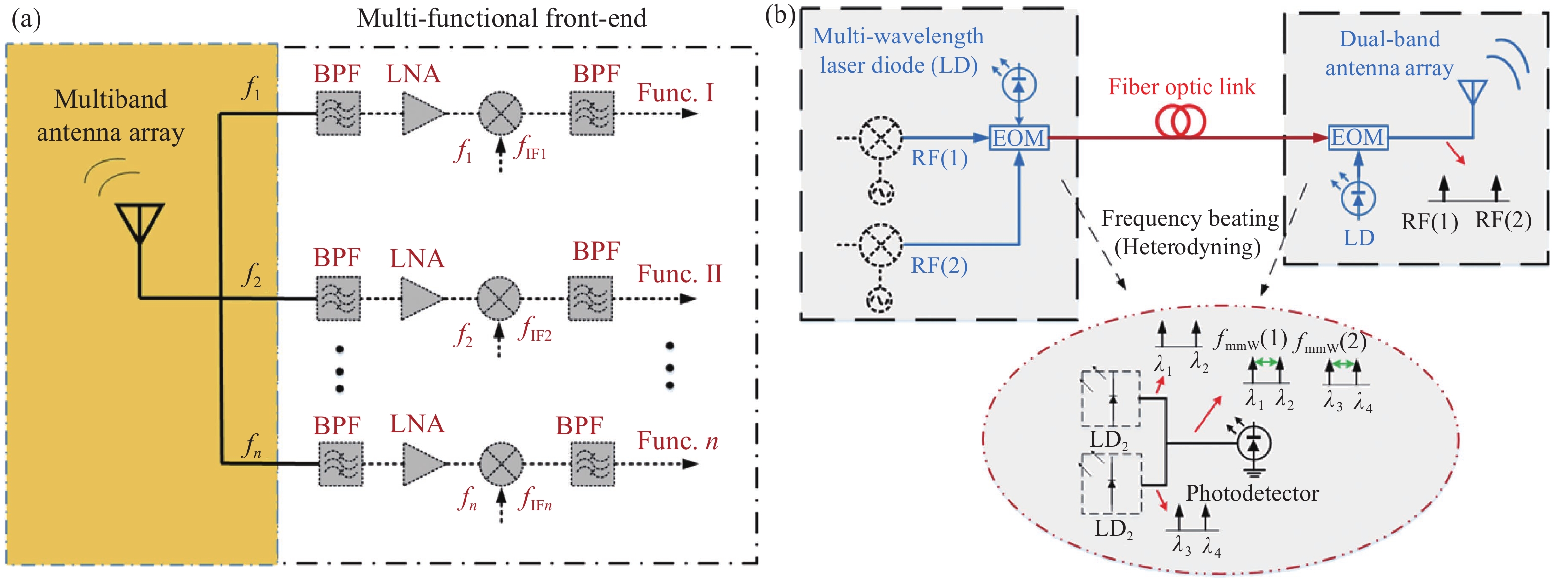
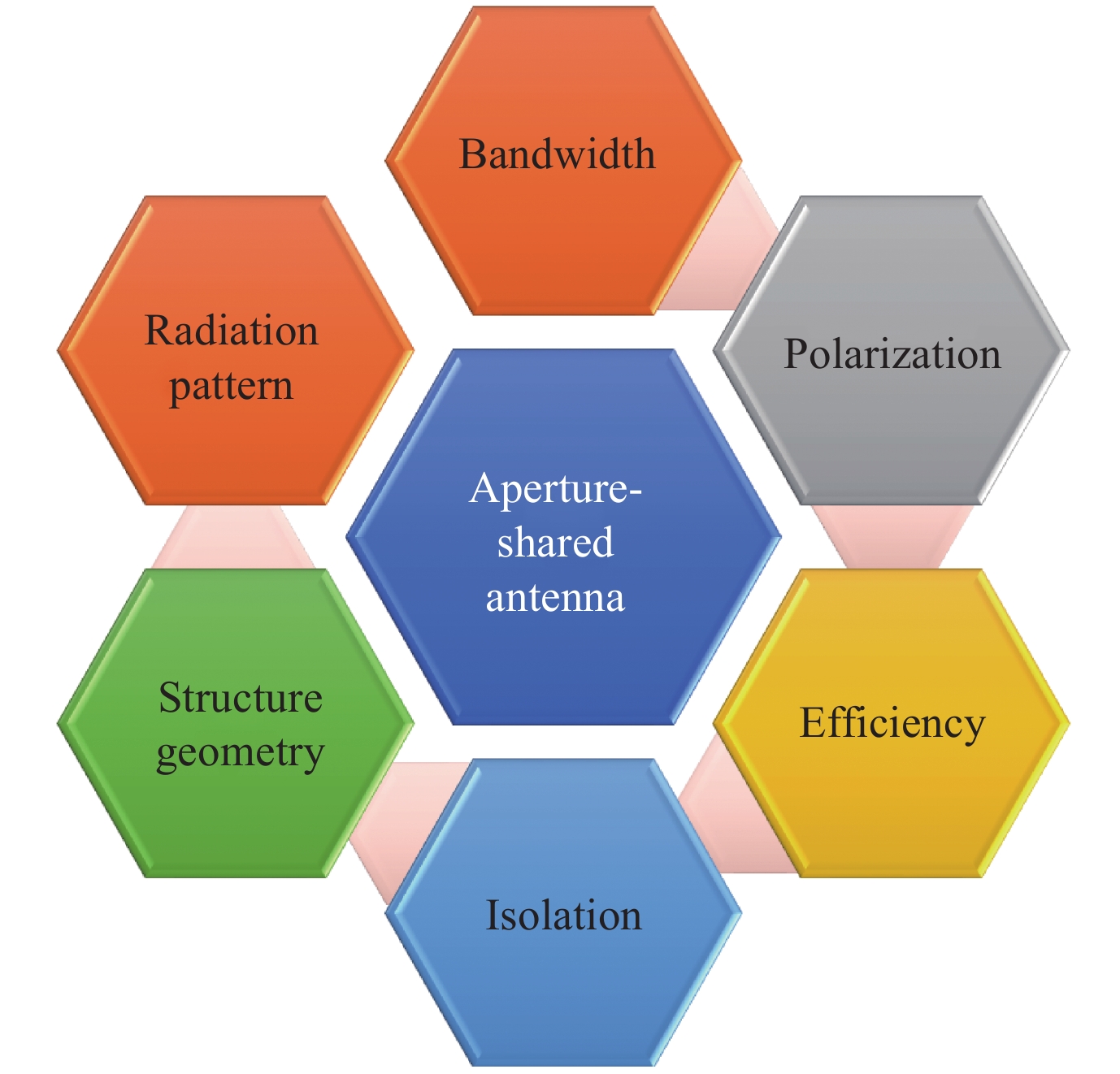
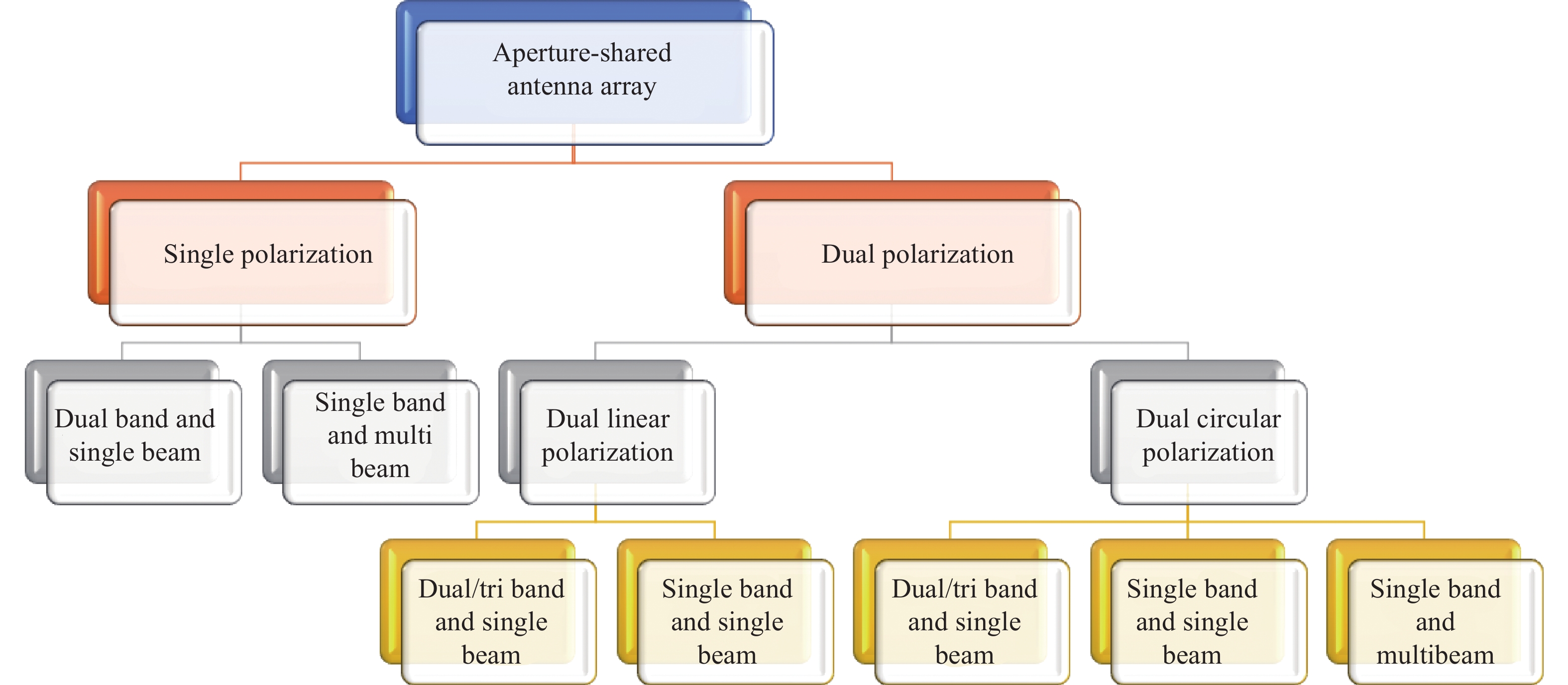
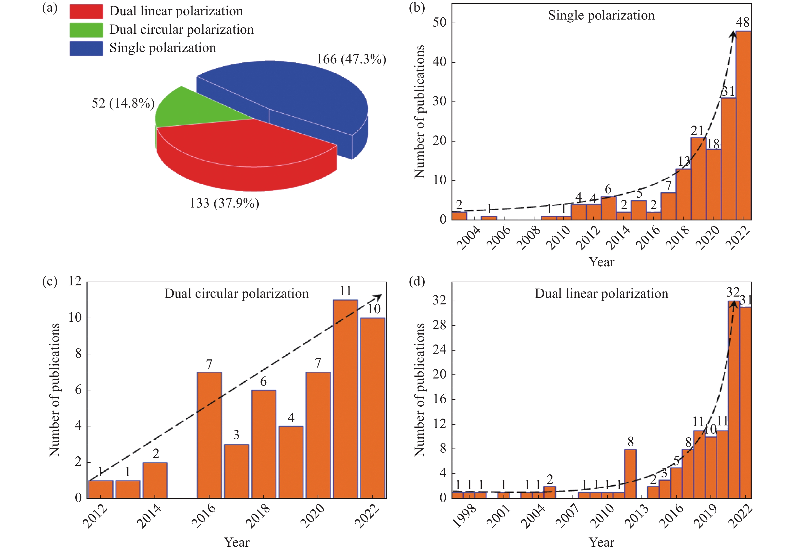
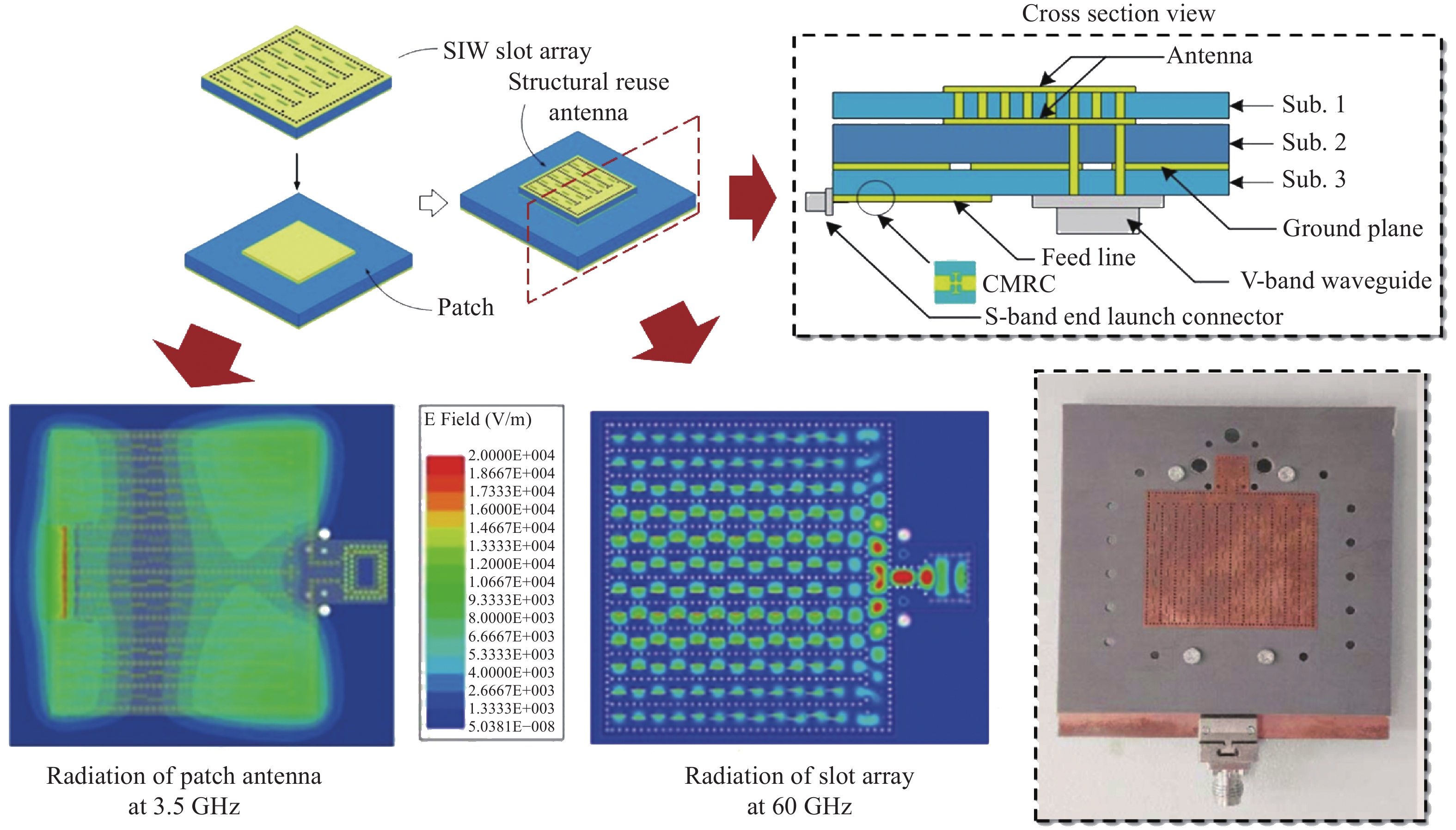
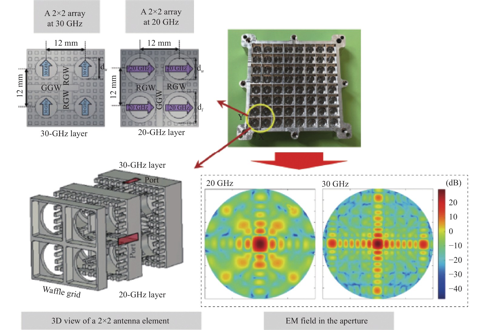
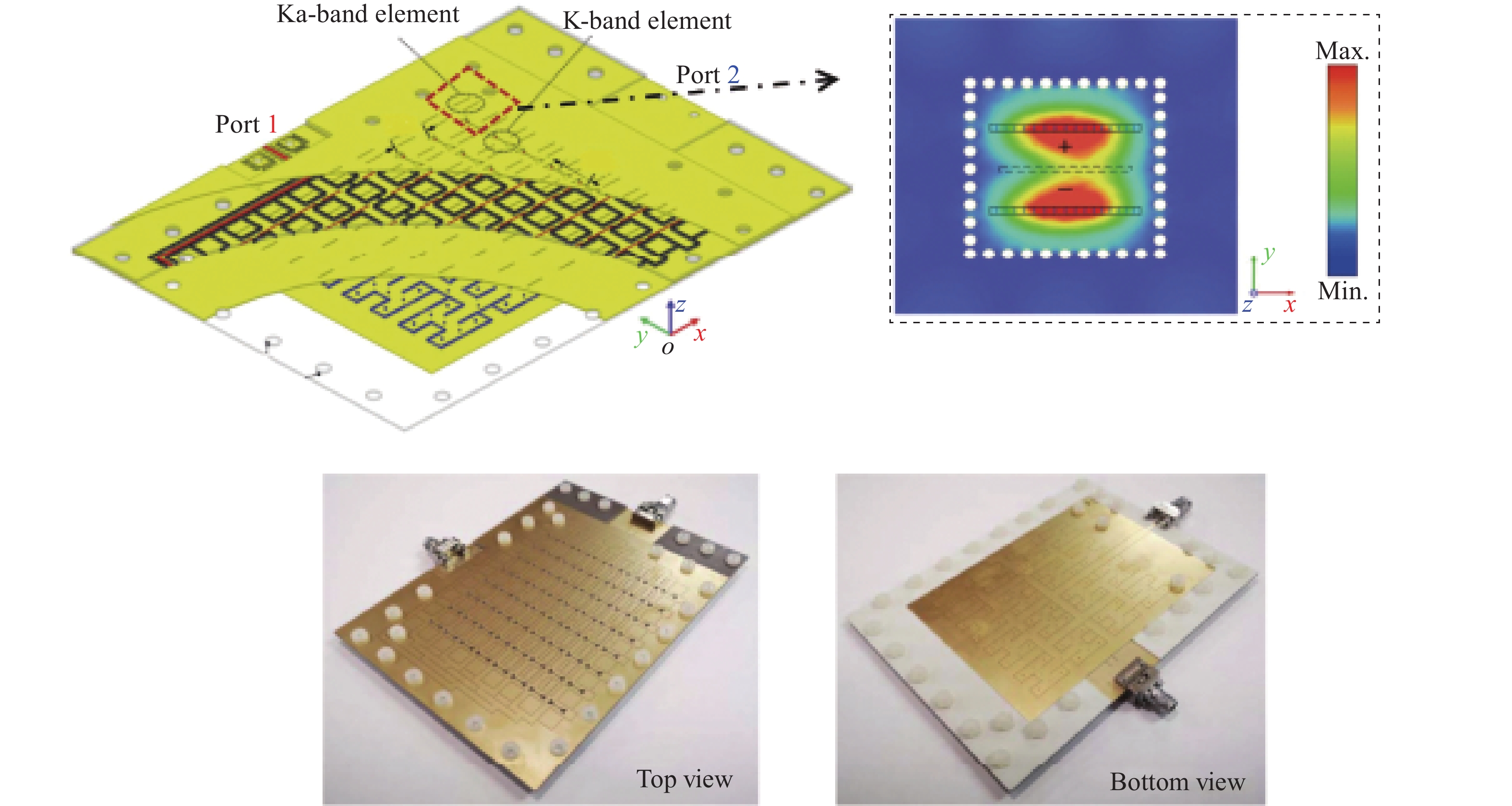


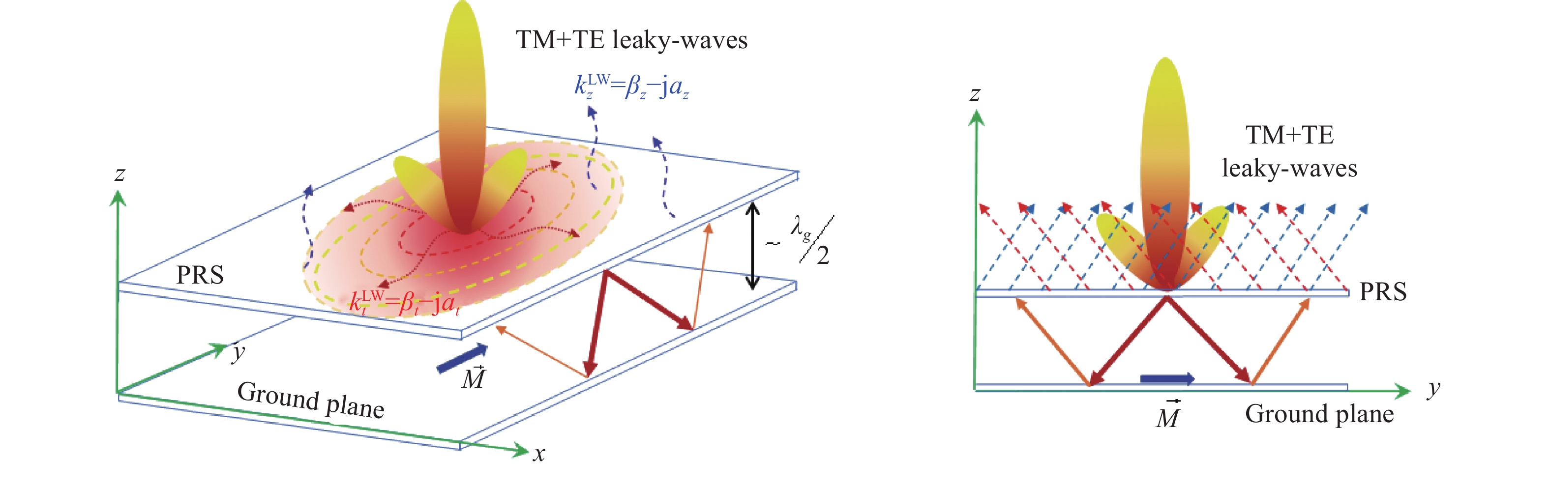
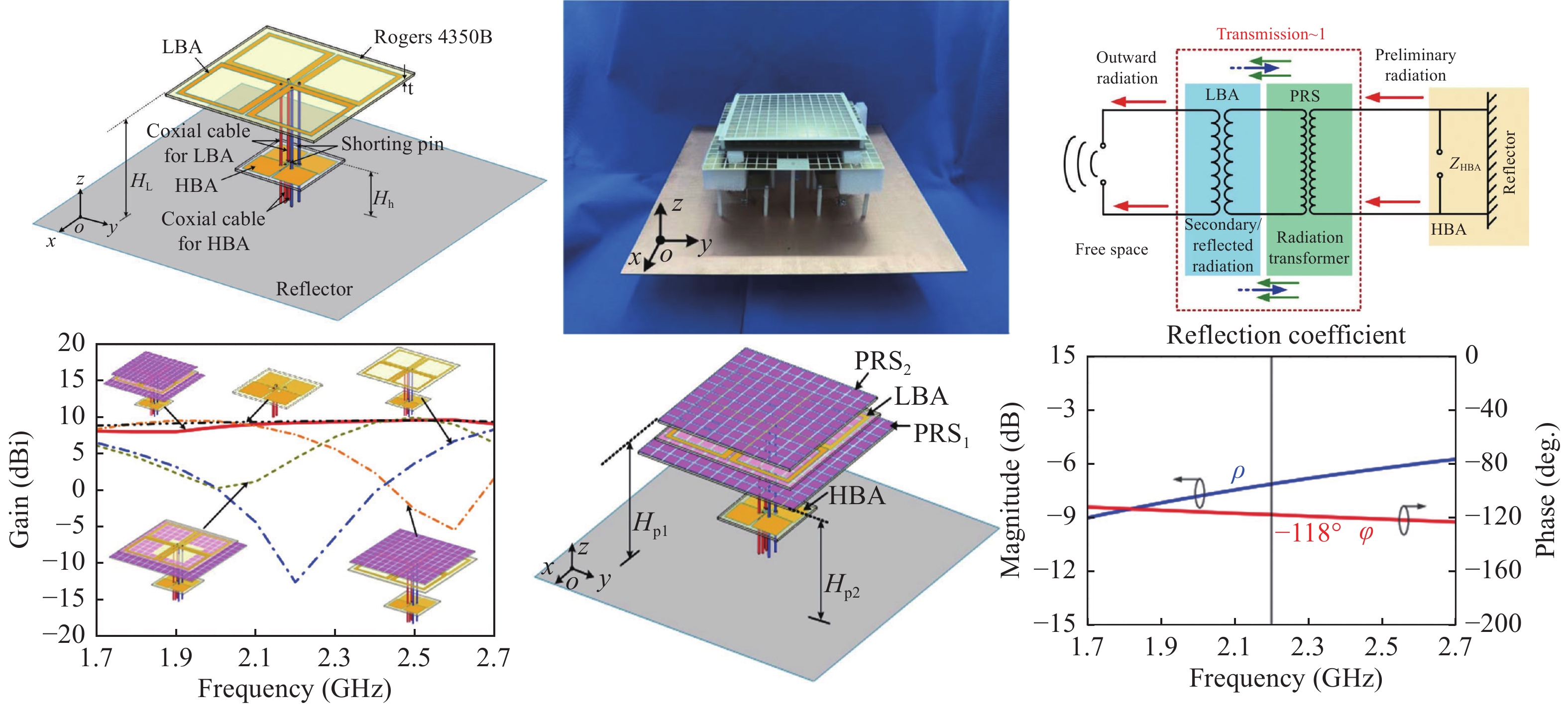
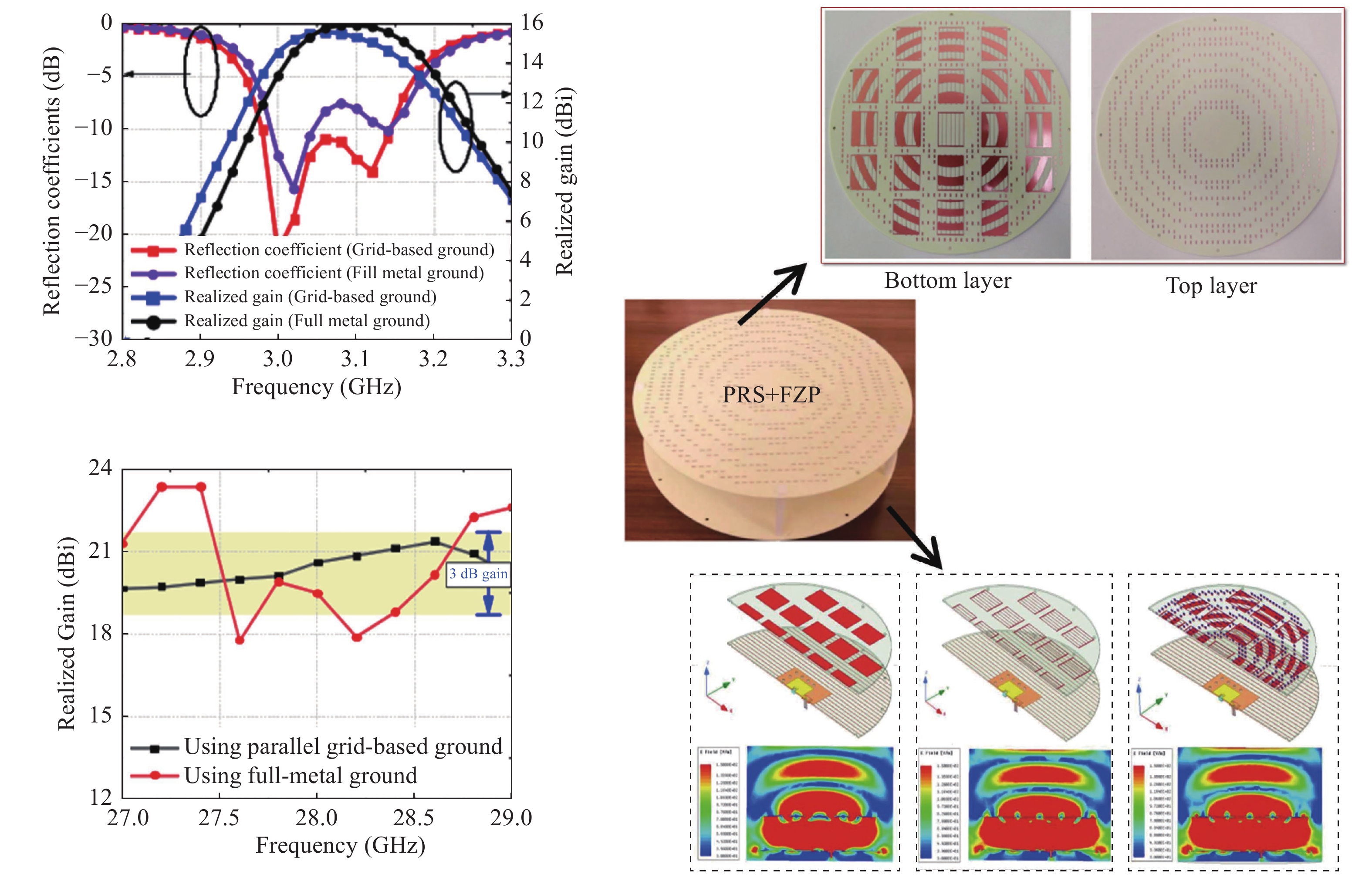

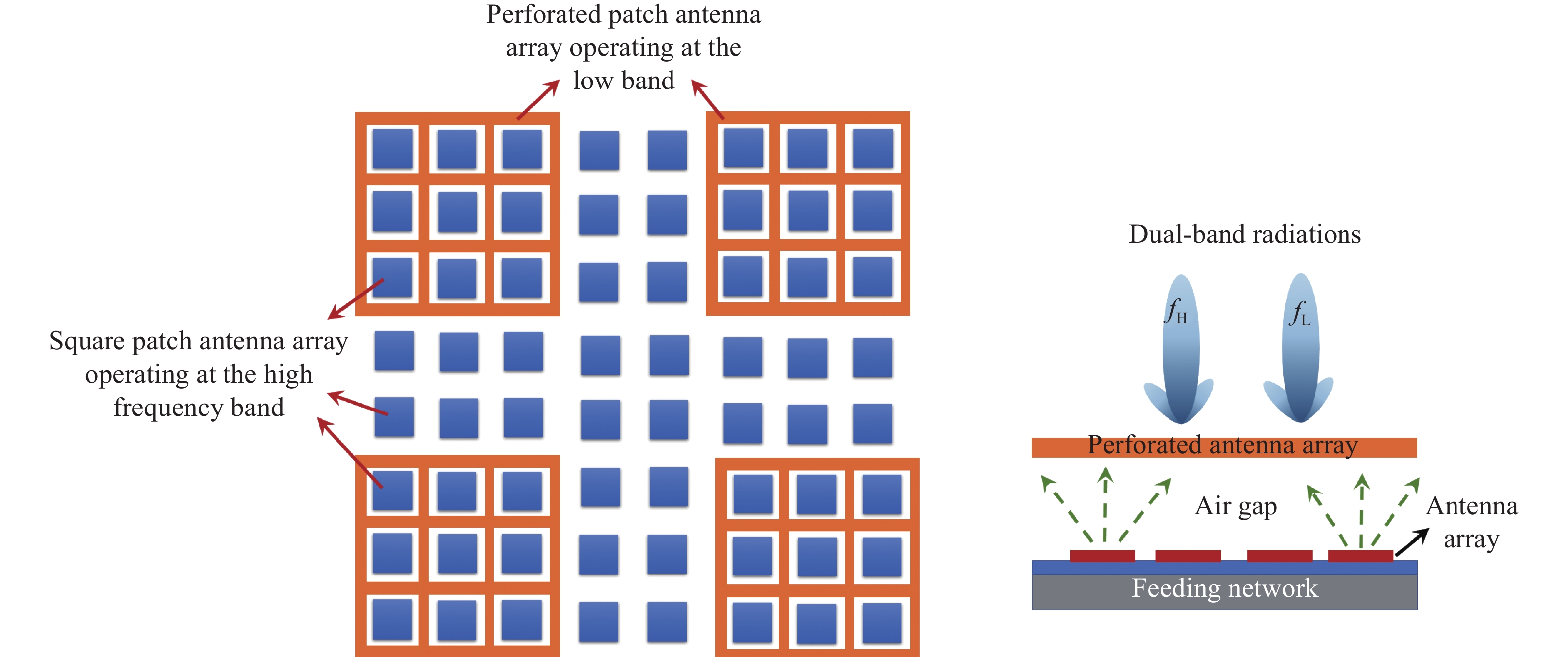
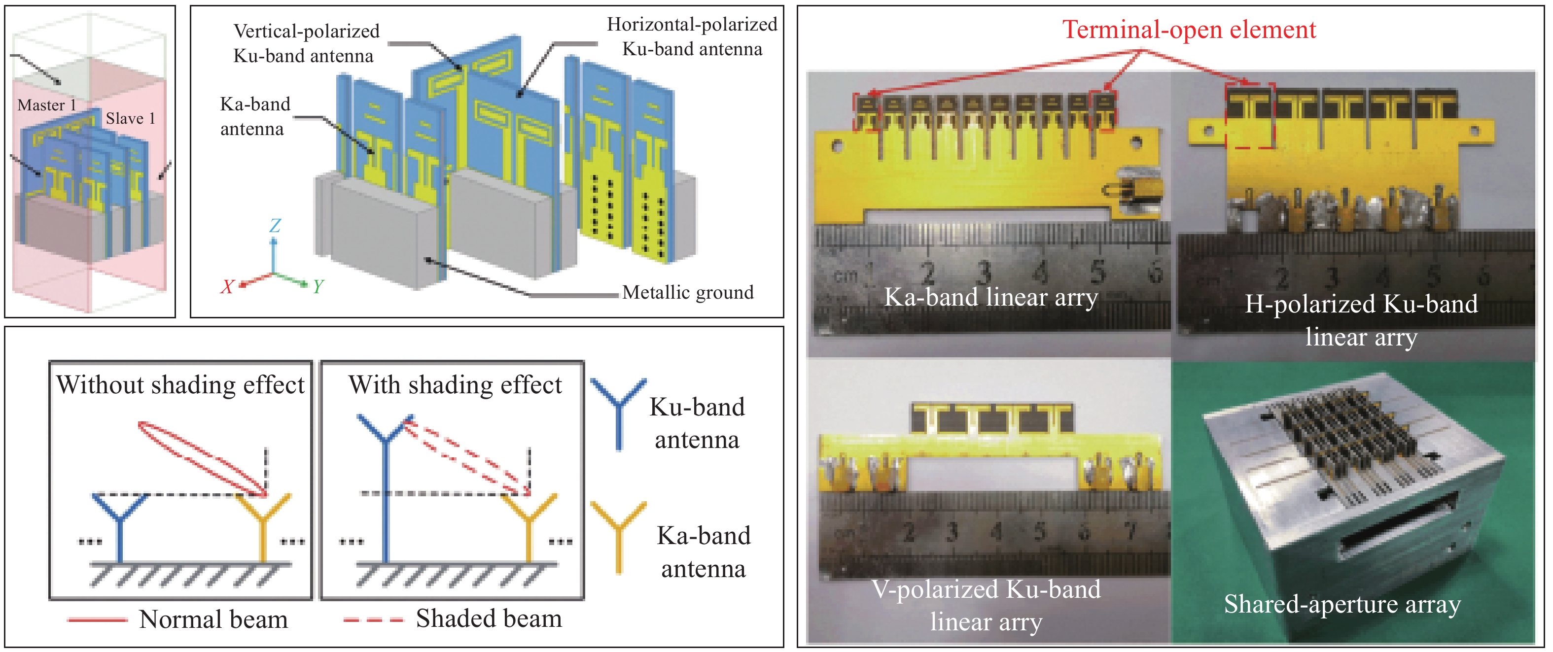
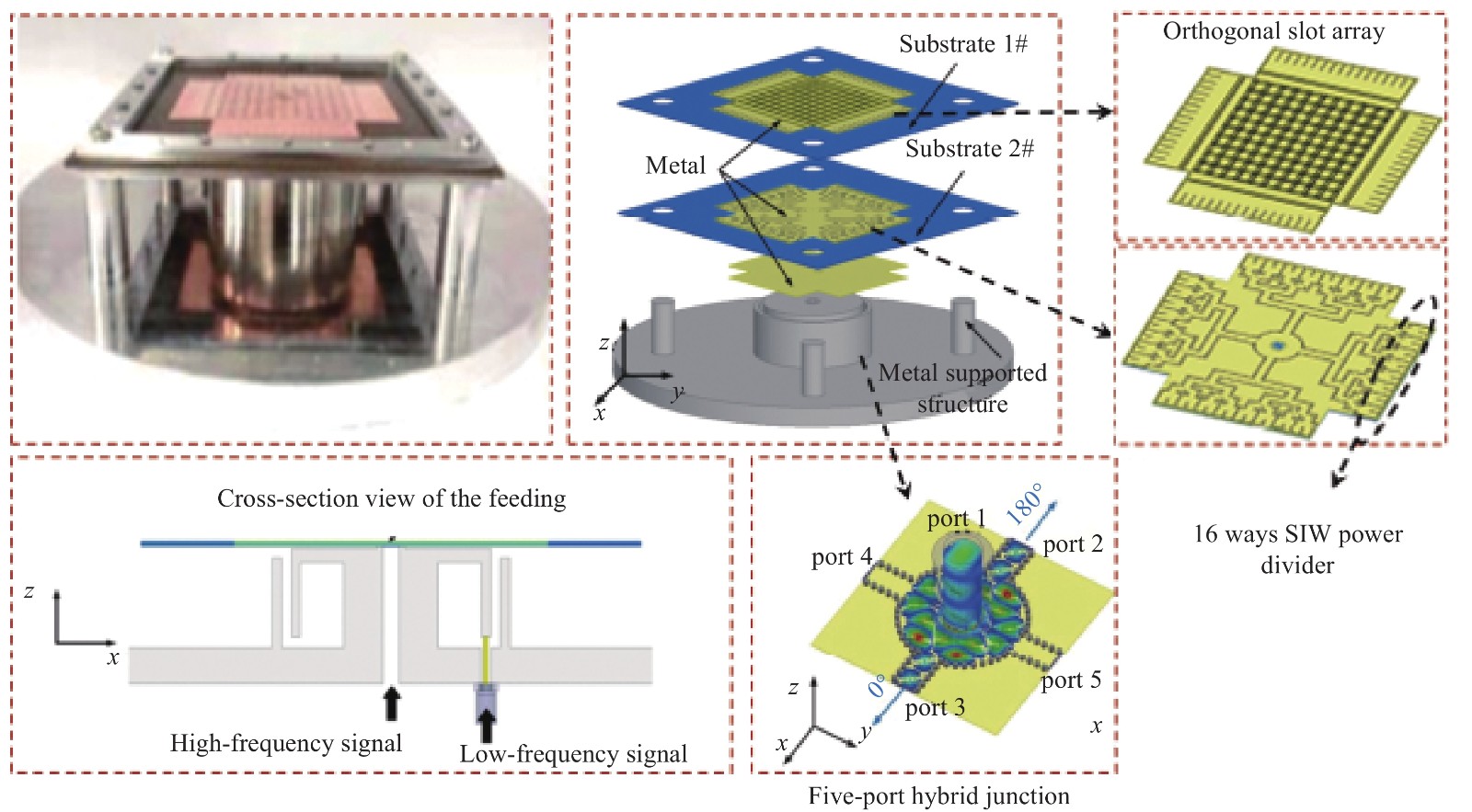
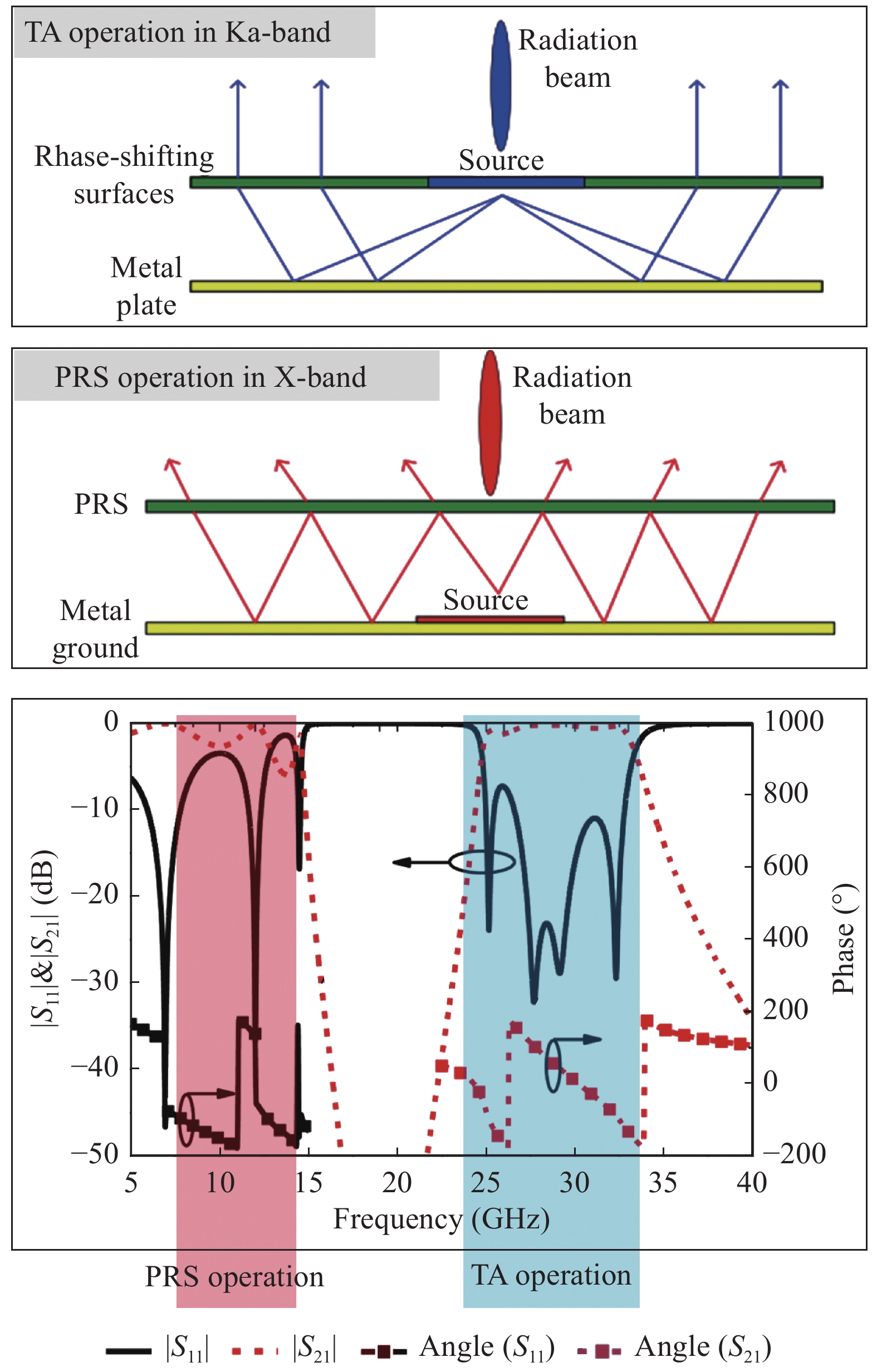
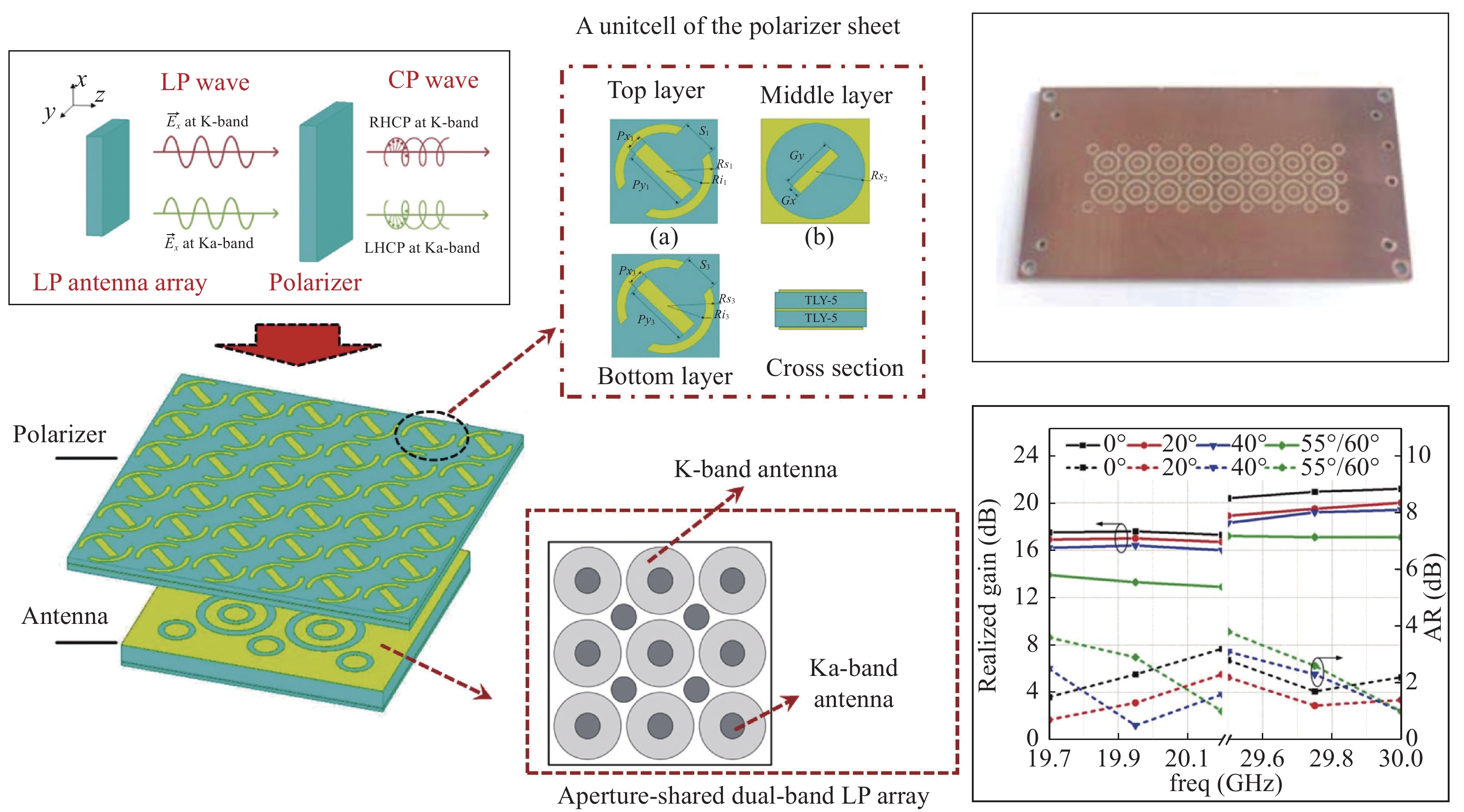
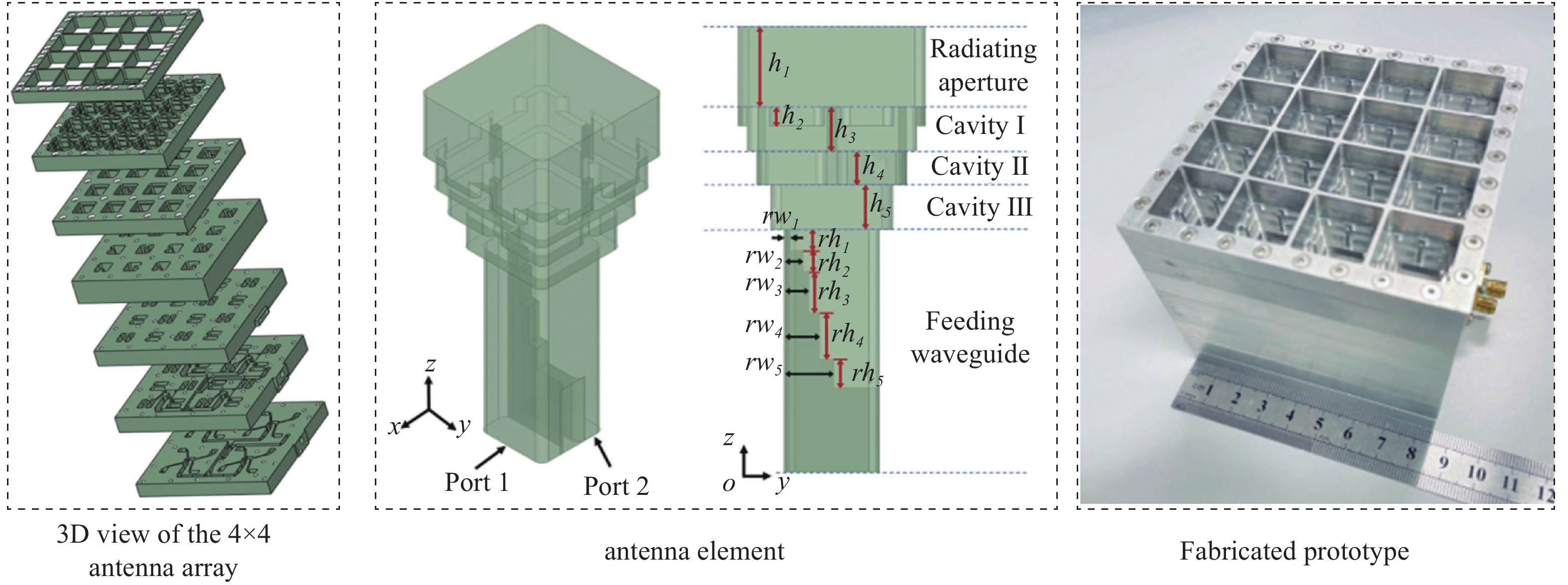
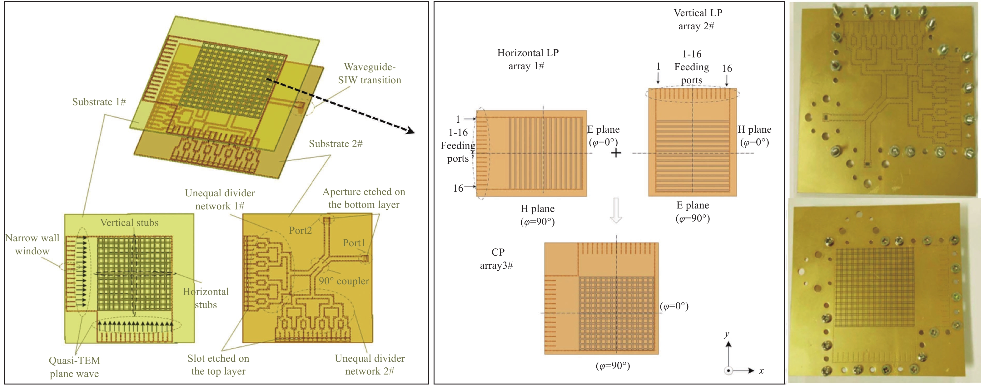
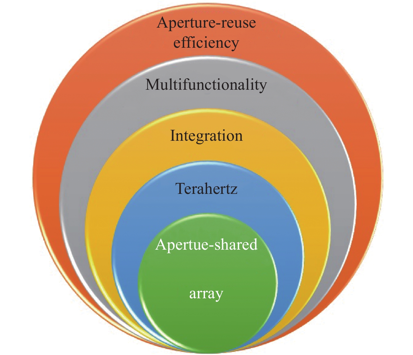


 DownLoad: